
Remote Prototyping of FPGA-Based Devices in the IoT Concept during the COVID-19 Pandemic


1
Department of Computer Science and Telecommunications, Poznan University of Technology, Piotrowo 3, 60-965 Poznan, Poland
2
Department of Computer Science, Opole University of Technology, Proszkowska 76, 45-758 Opole, Poland
*
Author to whom correspondence should be addressed.
†
These authors contributed equally to this work.
Electronics 2022, 11(9), 1497; https://doi.org/10.3390/electronics11091497
Submission received: 11 April 2022
/
Revised: 4 May 2022
/
Accepted: 5 May 2022
/
Published: 7 May 2022
(This article belongs to the Special Issue Dependability of Emerging Computing Paradigms and Technologies in IoT-Oriented Circuits, Architectures and Algorithms)
Abstract
:This paper presents a system for the remote design and testing of electronic circuits and devices with FPGAs during COVID-19 and similar lockdown periods when physical access to laboratories is not permitted. The system is based on the application of the IoT concept, in which the final device is a test board with an FPGA chip. The system allows for remote visual inspection of the board and the devices linked to it in the laboratory. The system was developed for remote learning taking place during the lockdown periods at Poznan University of Technology (PUT) in Poland. The functionality of the system is confirmed by two demonstration tasks (the use of the temperature and humidity DHT11 sensor and the design of a generator of sinusoidal waveforms) for students in the fundamentals of digital design and synthesis courses. The proposed solution allows, in part, to bypass the time-consuming simulations, and accelerate the process of prototyping digital circuits by remotely accessing the infrastructure of the microelectronics laboratory.
1. Introduction
The COVID-19 pandemic forced the introduction of many restrictions to limit the number of infection cases and the spread of the virus. One of the key restrictions during the first lockdown was to deny access to university buildings and to the research and laboratory infrastructure, which is also used for teaching purposes. Designing FPGA (Field-Programmable Gate Array) microelectronic systems often requires physical contact between human beings and the prototype boards. This is necessary both to program the designed circuit boards as well to connect the laboratory instrumentation in order to physically verify the correct operation of the circuit boards. The most commonly used instruments for this purpose are digital oscilloscopes with built-in and stand-alone logic analyzers as well as external function generators.
COVID-19 was an unquestionable surprise to everyone and required the development of a new approach to both research and teaching [1], especially in the context of the IoT (Internet of Things) [2]. A combination of areas, such as the design of intelligent tutoring systems [3], implementation of distance-learning-support platforms into existing solutions [4], and adaptation of existing solutions to certain sudden changes, such as the COVID-19 pandemic, are beginning to play a special role in education [5]. Remote lecturing is, in general, not a problem.
Many commercial online conferencing platforms can be used for that purpose, and existing open-source solutions can be adapted by plugging them into the university network infrastructure. The critical problem that needed to be solved in terms of both teaching and research was the remote access to specialized laboratory equipment, e.g., prototype boards with FPGAs, the monitoring of oscilloscopes and logic analyzer readings, located permanently in a specialized laboratory of microelectronic circuits and systems.
The implementation of new technologies in university teaching should ensure the continuity of teaching [6] while maintaining an appropriate level of education [7], recognizing the opportunities arising from the use of the IoT in education [8] and allowing for better access to education by students living far from the institutions of higher education or during periods of regional military conflicts [9]. The development of virtual and remote laboratories has become a key issue in the last two years for conducting efficient teaching and learning, particularly in medicine [10], cyber physical system co-design [11], and the use of augmented reality in accessing science labs [12].
Advanced and sophisticated online platforms are being increasingly used by the top-ranked universities [13]. The problem to be solved was both the conceptual and practical development of a system providing remote access to the microelectronic laboratory to enable the users to interact not only with PCs but also with test boards containing FPGAs as well to provide a possibility of monitoring stationary instruments that are permanently located in the laboratory.
Teaching engineering courses with the needed hands-on laboratory exercises during the COVID-19 lockdowns presented truly challenging issues. Physical contact with the measuring and recording engineering equipment with adjusted settings is difficult to replace by computer simulation and modeling techniques. Similar challenges are found in teaching at medical universities, where hands-on laboratory exercises and hospital practices are crucial for future medical doctors, nurses and technical hospital staff dealing with both human beings and sophisticated and expensive medical equipment. Such issues have already been addressed in recently published papers throughout the world—for example, see the surveys of the remote teaching issues in biomedicine, chemical and civil engineering [14], electrical engineering [15] and medicine [16].
The system concept presented in this paper can find application not only in the fields of the design of digital systems, the synthesis of logic circuits and the design of embedded systems but also in the research on the experimental implementation using FPGAs in chaotic circuits used in image encryption [17] and in research on hardware implementation of FPGAs in continuous-time chaotic circuits, whose mathematical models allow the use of hardware tools combined with laboratory measurements [18].
The development of the solution presented in this paper is divided into three independent stages. The first one requires a proper configuration of dedicated software on desktop computers enabling remote communication with the laboratory. Software installed on laboratory computers should be able to stream video from the observed measurements (signals) of the real apparatus connected to the test board with FPGA and the board itself.
In the second stage, it is necessary to prepare a protypical stand consisting of a board with FPGA connected to a PC. Specific output ports of the test board must be connected to an oscilloscope or logic state analyzer in advance. The third and final step is to mount two cameras facing the front panel of the measuring device and the FPGA board. The cameras are to be controlled by video streaming software. In this way, the remote user can simultaneously view the FPGA board as well as the current readings of the apparatus located in the laboratory room.
The novelty of the presented solution is supported by the fact that there are no known commercially available systems that would allow for remote access to the educational digital circuit prototyping laboratory. Most of such solutions are created ad hoc. It is worth noting that the remote workspace presented in this paper consists of a combination of professional design tools, open online elearning access and a popular platform for video streaming. The paper is organized as follows. In Section 2, the IoT concept for remote communication with laboratory devices is presented. The PUT’s remote teaching platform is described in Section 3, followed by a presentation of the IoT system for FPGA programming and testing in Section 4. Two laboratory experiments in the remote circuit prototyping are described in detail in Section 5. Our conclusions are included in Section 6.
2. The IoT System Concept for Remote Communication with Laboratory Infrastructure
Before the pandemic, the laboratory and its infrastructure was planned for eight independent lab stands. Each stand includes a PC (with XILINX software installed), two monitors, a wooden shell with a drawer for storing measuring probes, wires, prototype contact plates, etc. At each workstation, there is an oscilloscope with a built-in logic analyzer and a waveform generator. During the lab experiments, students work in groups of two or individually. This depends on whether the subject taught is of a fundamental or advanced level, perhaps with a team problem-solving task and/or complex circuit designs.
The challenge for the teaching staff is to provide the best possible access for students to the laboratory infrastructure. In particular, the development of the concept and implementation of the system architecture for remote access took place under not only heavy time pressure (the short time period available) but also the desire to use the available equipment to avoid extra purchases of the lab tools. One of the main motivations for developing such a system was to maintain student education at the same high level as observed before the COVID-19 pandemic lockdown as well as to give students a hands-on-like experience.
Computer simulation systems do not create an adequate sense of student exposure to the hardware of the systems being accessed in a real laboratory setting. However, a remotely accessed system with viewing webcams allows us to retain at least some of the didactic elements that come from real physical contact with the electronic devices. Figure 1 shows the designed system for remote design following the IoT strategy of the FPGA based systems. Access to the system is possible through an authentication at a firewall that restricts access to the university’s internal network by unauthorized users. Only students and staff members with active email accounts can access the system.
In the case that a lab instructor wants the students to have a look only at the FPGA test board, then there is a possibility to use all eight workstations available in the laboratory room. In principle, each workstation uses one webcam only. If the instructor wants the students to have an actual view of both the FPGAs and measuring devices (e.g., an oscilloscope), then only four stands are available, because, in such a case, each stand has to use two webcams (one for the FPGA and another for the measuring device). This restriction to four stands can be easily removed in the near future by adding more webcams in the laboratory room.
Figure 2 shows one FPGA-based remote electronic system design stand. Each of these stands has two video streaming channels—the first to view the FPGA test board and the second to view the video stream from the camera pointed at the oscilloscope. Due to certain priorities in the development of the stand and financial constraints, the components used—the mechanical arm and webcams—are not of the highest quality; however, the quality is sufficient for the purpose of teaching.
For the purpose of advanced research, more sophisticated tools would be needed. The total time required for an instructor to reconfigure the cameras and reorganize the camera boom mounts is about 30–40 min. Each computer has an identical image with the operating system and software installed. The popular Open Broadcaster Software (OBS) environment was used for streaming. OBS is a free and open-source software for video recording and live streaming.
It should be noted that the electronic equipment may have COVID-19 virus present on the desk surfaces, computers, FPGA chip boards, oscilloscopes and cameras. Unfortunately, the laboratory equipment is not resistant to the deposition of biologically infectious material. The COVID-19 virus can persist on a variety of surfaces according to microbiology studies, in particular on smartphones and laptops [19], desk surfaces [20], as well as on certain surfaces of reusable medical tools [21].
3. A Platform for Remote Teaching at PUT
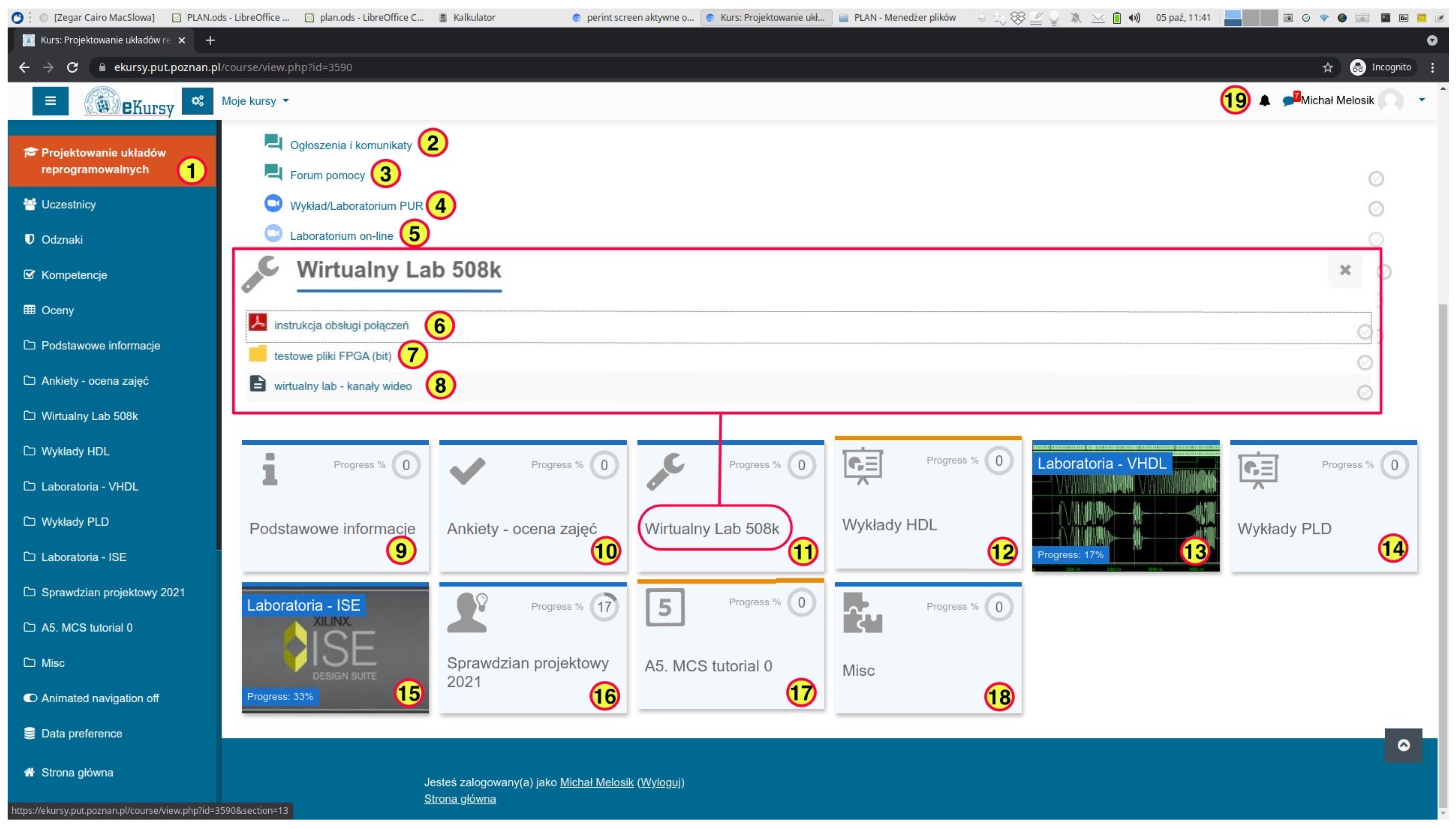
For the purpose of distance learning, our university designed an online platform ’ekursy’ (or ’ecourses’ in English) via which teaching materials are made available to students. Each subject taught has a separate section that can be freely modified by any instructor. It is possible to create sub-sections of each course with embedded online resources, such as the assignments, remote connection links, audio-visual contact with the instructor and sample files for programming test boards with FPGA. Figure 3 shows the main screen view of the Fundamentals of Digital Design and Synthesis course.
In the central part, the submodule virtual lab (’Wirtualny Lab 508K’) is exposed. 508K is the room number. This module contains instructions for remote connection to the infrastructure of the specialized laboratory, demo files to program the test board to verify the correct operation of the desktop kit. In other sections, the materials used during lectures, the lab exercises to be performed and certain projects are assembled. Bearing in mind that the installation and configuration of XILINX software can be a problem (especially for weakly prepared students), a virtual machine image for the VirtualBox (cross-platform virtualization software) is available, so that those students can use this virtual system for simulation tasks without remotely accessing the laboratory computers (as a pre-lab task).
The popular twitch.tv platform was used to embed the video streams. When choosing the streaming platform, the priority was to ensure full functionality of the system in a relatively short period of time. Teaching the design of systems based on FPGAs varies depending on the major and university. In some majors, the curriculum is organized so that students gain knowledge of the basics of digital electronics using FPGA reprogrammable circuits in preliminary courses.
Students may learn to design combinational and sequential circuits. This learning is based on using schematics and pre-defined logic components, which are both available in XILINX ISE software libraries and prepared by the instructor. This type of courses in remote-learning mode can be done entirely based on simulation by using, for example, the ISIM or ModelSim simulators. The physical lack of contact with the university laboratory infrastructure does not translate into a drastic lack of knowledge and skills in the design of basic digital electronics circuits.
Knowledge of basic digital electronics allows students to gain familiarity with hardware description languages, such as VHDL, in the subsequent semester. Students learn how to design behavioral digital systems. These classes can be held using CAD tools from XILINX or ModelSim. Furthermore, such a course does not require the physical contact of students with the laboratory infrastructure. The skills of using VHDL syntax are needed for more advanced courses. Likewise, the studies conducted with only the VHDL-AMS based simulations do not require physical contact with the laboratory devices, if used for simulation of mathematical models for chaotic circuits [22], circuits with memristors [23], simulation studies of integrated filters in CMOS technology [24] and the simulation of video processing circuits [25].
The further educational path assumes the broadening of students’ knowledge and skills in the area of digital systems design with a particular emphasis on hardware synthesis design skills. Some of the classes and assignments within the subjects belonging to this thematic group may also be conducted completely remotely. Unfortunately, the key to gaining advanced technical competences is to provide students with physical access to the laboratory infrastructure. The COVID-19 pandemic forced universities worldwide to impose obvious sanitation restrictions, which resulted in the educationally critical problem of students not interacting physically with lab equipment.
4. Managing an IoT System for FPGA Programming and Testing
Students have 24/7 access to the system in Figure 2. To access the system, a student must log through the firewall (hellfire.put.poznan.pl). The access is authorized by entering the email address and password obtained from the university network system administrator. After such access is granted, the course materials are available through a standard login (user+password) at ekursy.put.poznan.pl.
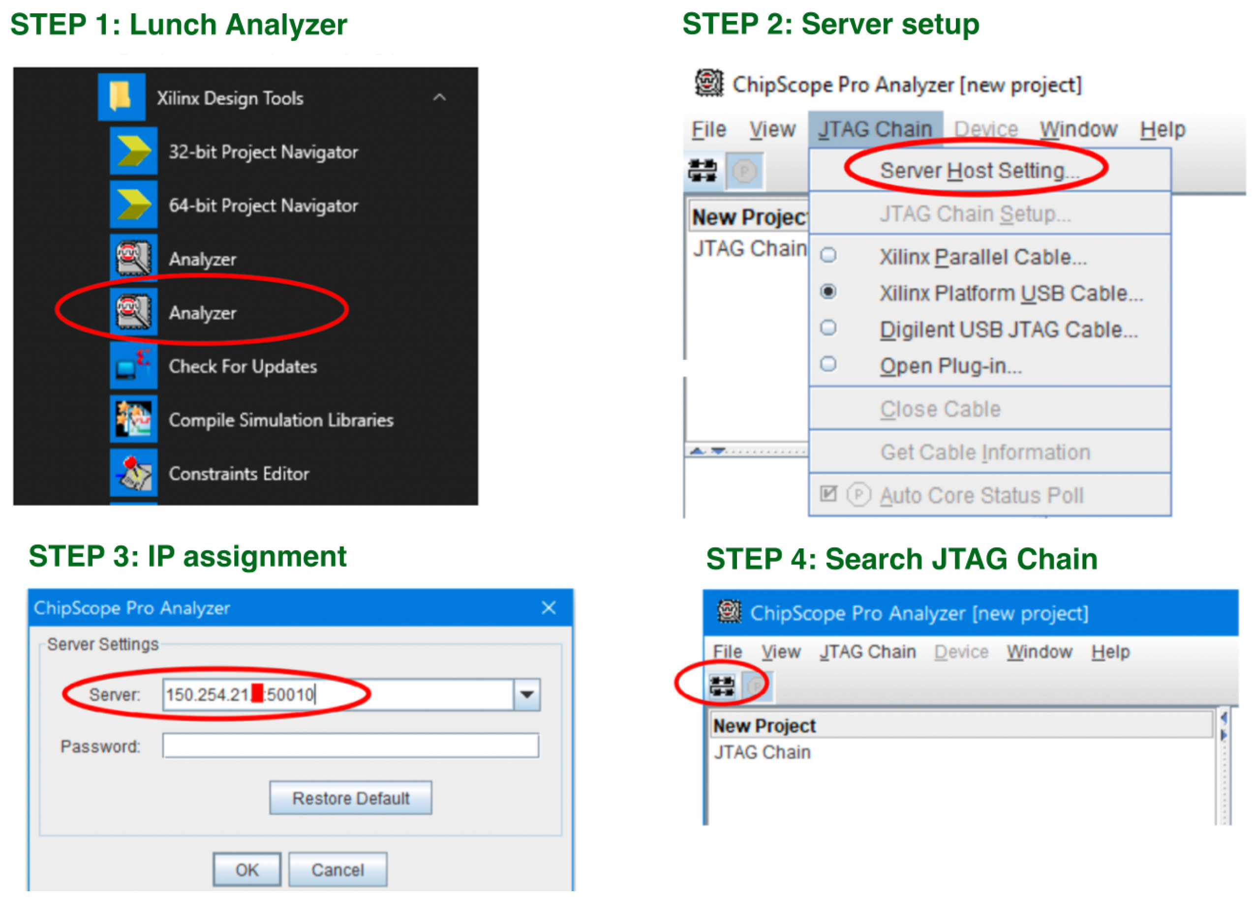
Figure 4 shows the steps required to remotely program FPGA. All the programs needed for remote work in the lab were configured on a virtual machine available on the course website as mentioned earlier. The student begins by establishing a VPN connection to the PUT network. Users with student account restrictions should have permissions set to establish connections to the appropriate TCP ports on the lab subnet. In case of doubts, students are advised to contact the instructors in charge. The next step is to run the Analyzer program. The Analyzer is executed from the Xilinx 64-bit tools group (see Figure 5).
The procedure is as follows: in the program’s interface, set the server address with the appropriate TCP port number, first, by checking which stations are active (previews of the video streams are available on the course page). The available IP addresses are from 150.254.21.2 to 150.254.21.9, TCP: 50010. In the next step, a connection with the Cse server should be established. In order to do that, one should establish a connection with Search JTAG Chain command.
Once the test board is programmed, the running test configuration of the FPGA is visible through the visual preview (in the OBS environment) as shown in Figure 6.
If successful, the detected JTAG chain will be displayed. Depending on the platform, the list of devices present may vary. The successful connection message should also be visible in the server console in the return video feed—a list of the video stream addresses is available on the course page. After a successful connection is established, the student should test the efficiency of the board with the FPGA chip physically available on the lab stand. To do this, it is recommended that a load of a test bit file is uploaded. Each prototype platform type has a unique test batch downloadable from the course page. Attempting to configure the FPGA with an inappropriate .bit file will fail without damaging the board. The .bit file names correspond to different types of FPGA chip platforms.
5. Demonstrations of Programming and Testing of Microelectronic Systems
5.1. Remote Designing and Testing of the DHT11 Sensor
The objective of this task is to display the current surrounding’s temperature and humidity level on the LCD display integrated with the Spartan 3E Starter Kit. On the basis of the technical documentation of the sensor that a student has to design using VHDL language, a module operates this sensor and displays the temperature and humidity readings on the LCD integrated with the digital board.
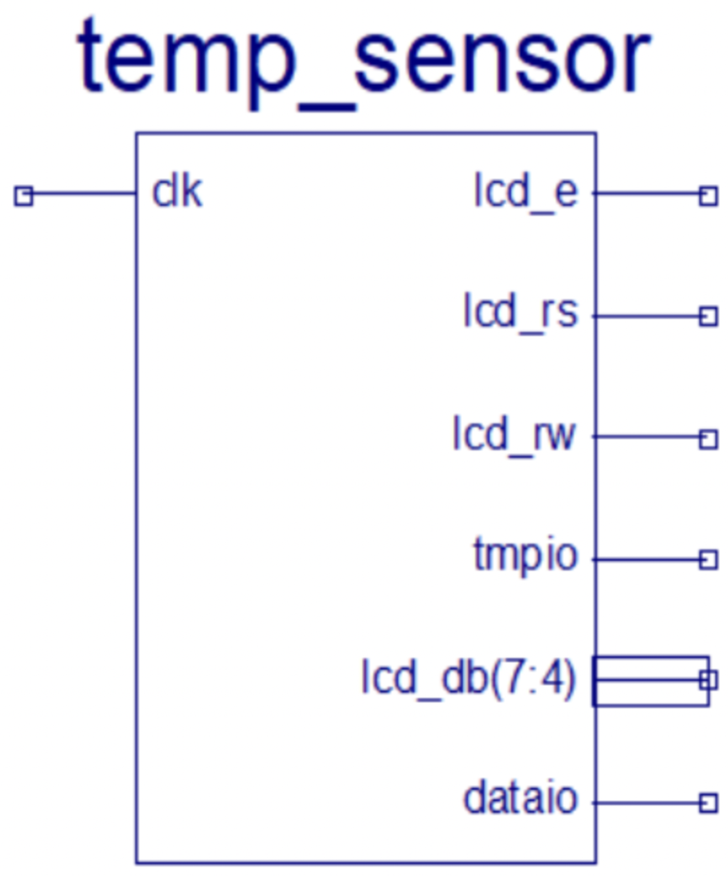
The DHT11 sensor is permanently connected to the Spartan 3E Starter Kit. The student’s task (described in the lab manual and the Spartan 3E Starter Kit) is to identify the ports to which the sensor is physically connected. This is necessary to specify the ports in the ucf file. Figure 7 shows the symbols of the module designed for the DHT11 sensor. This symbol is generated automatically based on VHDL source codes using the XILINX ISE WebPack design environment. The clock is at 50 MHz with a —input/output port for communication with the temperature and humidity sensor DHT11. The output signals are —start display, —restart display, —read/write signal from/to display, —signal to send data and commands to display and read data and —signal to preview the sensor signal, which is used in the chipscope to show what the present reading from the sensor.
The designed module in Figure 8 includes the following components and their functions:
- The DHT11 module reads the temperature and humidity and outputs them in binary forms.
- The BIN2BCD module—converts binary value to decimal form (there are two of them—one for temperature and one for humidity).
- The frequency divider module—generates the 1 MHz frequency signal for communication with the DHT11.
- The LCD driver—generates the text with the values generated by BIN2BCD.
Students have to submit written reports on the completion of the task, which are then uploaded to a dedicated section of the platform at ekursy.put.poznan.pl. In the report, the students provide copies of the screen confirming that the physical device worked remotely in the lab and a full set of source files. A grade for the completed assignment is given and made available to the student through this platform as well.
5.2. Remote Designing and Testing of a Sinusoidal Waveform Generator
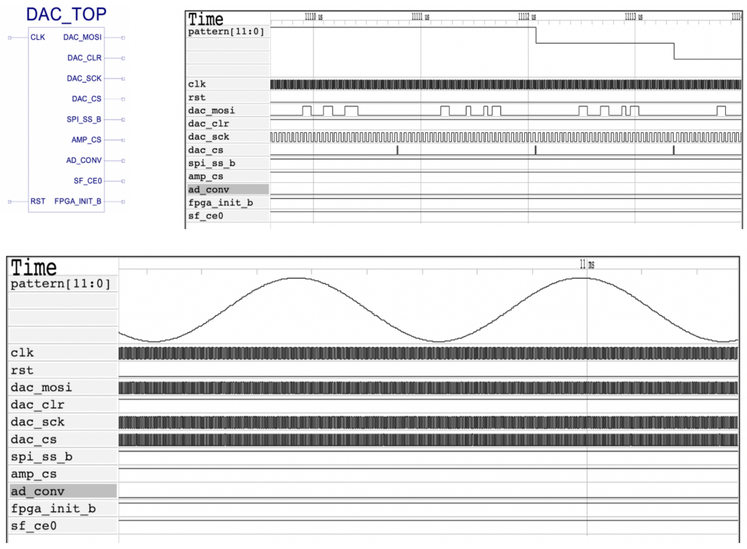
Students first need to read the technical documentation of the Spartan 3E Starter Kit, including a description of the DAC ports. The designed sine wave generator module returns a 12-bit signal and sends this value to the DAC controller. The DAC controller generates serial commands and data to the DAC using SPI transmission. The frequency divider is designed to generate a clock signal according to the successive samples of the sine wave signal being changed. The designed sine wave generator module is shown in Figure 9.
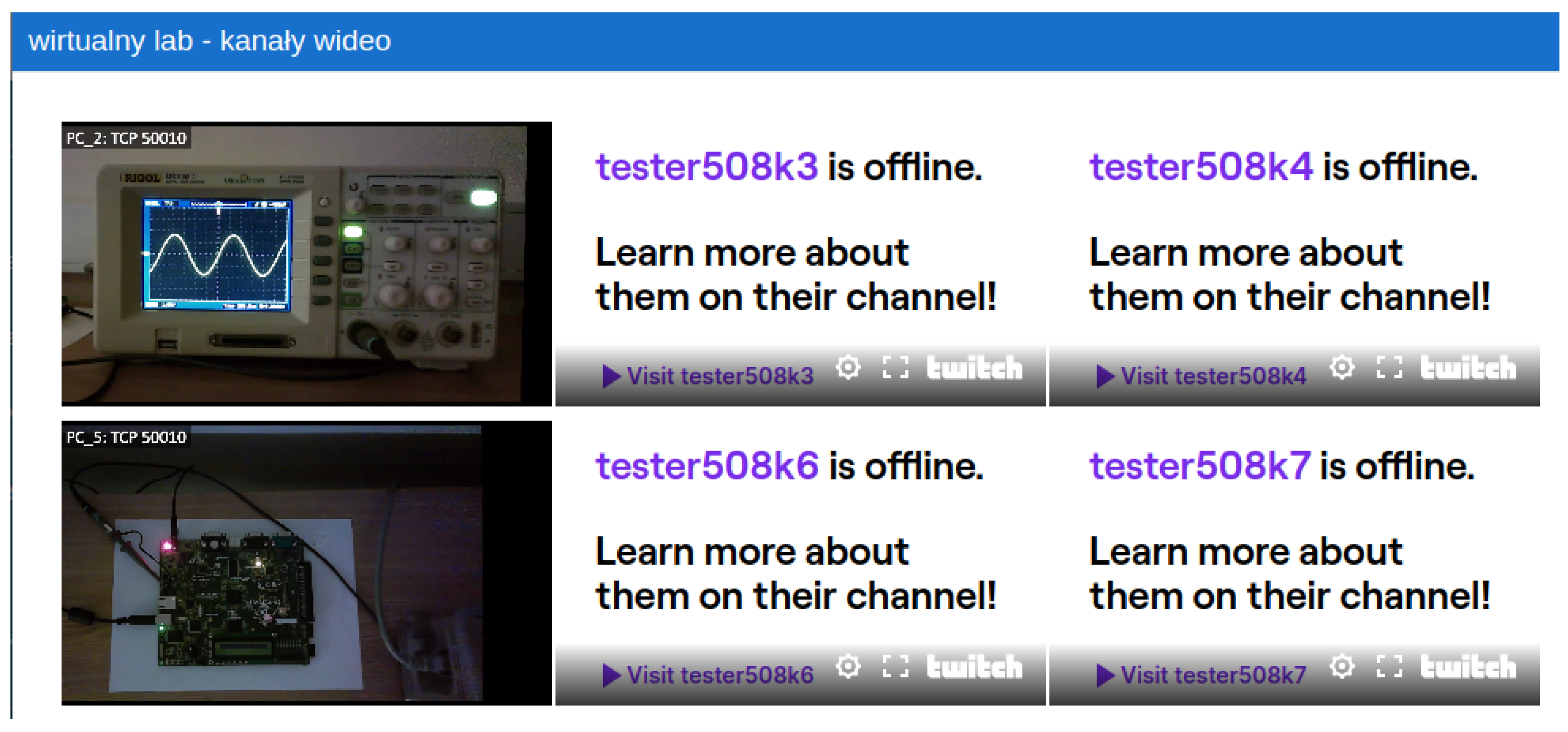
After remotely programming the test board with the FPGA, the student obtains a real-time preview (with a delay of up to several seconds) of the readout of the video stream from the camera pointed at the test board with the FPGA chip and the video stream of the camera pointed at the oscilloscope’s faceplate. Figure 10 shows a section with a preview of the video feeds available in one of the ’ekursy’ tabs. The twitch.tv platform was used for streaming, and the streaming channels were integrated into the ’ekursy’ platform under the link available in the ’virtual lab’ module. For the purpose of this article, only two channels are shown. The rest of the channels are not launched.
One of the nontrivial problems faced by the teaching instructors was the issue of the proper lighting of the test board itself and the oscilloscope. The method of lighting varied throughout the day depending on the time of day and the availability of sunlight in the lab room. The inclusion of overhead lighting in the room is not quite in line with the recommendations of the building administration (in a 24/7 setting). As an alternative, mini USB lights can be used. For this purpose, it is necessary to mount the USB extension cord above the webcam to the mechanical arm.
Nevertheless, such solutions may cause reflections on the surface of the printed circuit board. These cameras, when permanently mounted, may change their positions, which causes the reflection to be transferred to the LCD screen. Disconnecting the USB lamps may cause the visibility of the video stream from the test board to be weaker during the evening hours. These are the problems that have already arisen during practical use of the system. However, it was observed that the reduced lighting in the lab room did not affect the readability of the oscilloscope screen readings.
6. Comparative Analysis of the Proposed System with Other Similar Solutions
Table 1 shows a comparative analysis of the remote teaching systems presented in this paper and other similar systems presented in the literature. The Digital Object Identifiers of the first seven papers are given in the caption. The table illustrates various features of the seven proposed solutions in comparison to the solution present in this paper (see the last row in Table 1).
It appears that the developers of platforms for the remote teaching of electronics are mainly focused on ensuring correct communication with the laboratory infrastructure. The least important feature for the developers seems to be an integration of the developed solution with the internal university network to be used as a platform for sharing teaching materials with students. Another feature that is neglected in the design of those solutions is to provide the students with a dedicated virtual machine image containing the configured environment to be run.
Few of the solutions focus on giving the students views of the laboratory equipment—for example, multimeters and oscilloscopes. The usability of only some of the analyzed solutions was confirmed by representative implementation examples. In some solutions, instead of viewing the real measuring laboratory tools, virtual programs imitating those tools were used for recording the results.
Considering the above features, our solution is, in some aspects, different and novel, as the proposed system is integrated with the university teaching platform and has been confirmed by two implementation examples, and its use does not pose problems for students—due to the pre-configured virtual machine image.
7. Conclusions
The main contribution of this paper is the development of the laboratory stands that allow the continuity of the teaching process during the COVID-19 lockdowns in the field of digital systems design with remote access to the measuring and recording laboratory infrastructure. Such stands give students a hands-on like experience. The usefulness of the stands was confirmed by two representative examples—the control of a temperature and humidity sensor and the generation of sinusoidal waveforms.
The lockdowns due to the COVID-19 pandemic presented a large challenge to the teaching of advanced technical courses, especially those in which physical contact between students and the laboratory apparatus was necessary. The sanitation restriction undoubtedly resulted in new experiences in every area of teaching and learning as well as private lives from both the technical aspects (e.g., the reliability of online teaching platforms) and the mental health issues of those involved. Students generally spent more hours in front of computers but were deprived of the possibility to go to the university buildings and thus of elementary physical contact with the lab recording and measurement equipment, which is crucial in most engineering majors.
In discussions on the impact of COVID-19 lockdowns on the quality of education, there are various opinions stating that the pandemic and lack of preparation for remote teaching resulted in lowering the results of teaching outcomes. Lockdowns may have significantly decreased the quality of teaching, especially where an interaction with specialized laboratory facilities was required. The adaptation of teaching to the remote mode required an increased number of hours spent by the teaching staff to prepare or upgrade the teaching materials.
The prior lack of health protocol regulations adequate to the pandemic situation forced the university administration to introduce certain new rules, e.g., maintaining an appropriate distance between students, wearing protective masks and gloves, using cleaning and disinfectant liquids and vaccination requirements. The system presented in this paper for the remote design and the testing of electronic systems based on FPGA is only one example of the new initiatives undertaken in a very short period of time.
The system, despite that it appears to be a temporary solution, proved, from the functional point of view, to be satisfactory to ensure the anticipated teaching outcomes in the case where there is a need for students to be physically acquainted with specialized hardware tools. Its effectiveness was confirmed by two demonstration projects that fully utilized the functionality of the system. The correctness of the functioning of the system was verified based on the tasks involving the use of the VHDL hardware description language and the designing of electronic circuits.
A hypothetical lack of the remote teaching lab discussed in this paper could, most likely, result in a decrease in the quality of teaching and lower learning outcomes, and consequently, in the accumulation of learning deficiencies that will show up in subsequent semesters. The developed system allowed for the realization of courses in remote synchronous or asynchronous modes, while minimizing the educational losses resulting from the lack of physical access to the laboratory apparatus.
The major limitation of the presented system is the inability to remotely unplug the oscilloscope probe from one pin on the test board and plug it into the other pin. The pin to which the probe will be connected must be previously set by the instructor. In order to remotely manipulate the oscilloscope probe, it would be necessary to design a system for remote mechanical robotic manipulation of the measuring instruments. This is one of the possible directions of further development and enhancement of the hardware of the system.
Author Contributions
Conceptualization, M.K.; methodology, M.M.; software, M.N. and M.K.; validation, M.M.; formal analysis, W.M.; investigation, M.M., M.N. and M.K.; writing—original draft preparation, M.M.; writing—review and editing, W.M.; visualization, M.M., M.N. and M.K. All authors have read and agreed to the published version of the manuscript.
Funding
This research received no external funding.
Data Availability Statement
All data and figures to support the presented topic are included in the paper.
Conflicts of Interest
The authors declare no conflict of interest.
References
- De Jong, T.; Linn, M.C.; Zacharia, Z.C. Physical and virtual laboratories in science and engineering education. Science 2013, 340, 305–308. [Google Scholar] [CrossRef] [PubMed] [Green Version]
- Daniela, L. The Internet of Things for Education; Springer: Cham, Switzerland, 2021; pp. 1–6. [Google Scholar]
- Gros, B. The design of smart educational environments. Smart Learn. Environ. 2016, 3, 1–11. [Google Scholar] [CrossRef] [Green Version]
- Moreira, F.T.; Vairinhos, M.; Ramos, F. Conceptualization of Hypersituation as Result of IoT in Education. In Ludic, Co-Design and Tools Supporting Smart Learning Ecosystems and Smart Education; Springer: Berlin/Heidelberg, Germany, 2021; pp. 67–73. [Google Scholar]
- Ożadowicz, A. Modified blended learning in engineering higher education during the COVID-19 lockdown—Building automation courses case study. Educ. Sci. 2020, 10, 292. [Google Scholar] [CrossRef]
- Salmerón-Manzano, E.; Manzano-Agugliaro, F. The higher education sustainability through virtual laboratories: The Spanish university as case of study. Sustainability 2018, 10, 4040. [Google Scholar] [CrossRef] [Green Version]
- Romero-Rodríguez, J.M.; Aznar-Diaz, I.; Hinojo-Lucena, F.J.; Gómez-García, G. Mobile learning in higher education: Structural equation model for good teaching practices. IEEE Access 2020, 8, 91761–91769. [Google Scholar] [CrossRef] [PubMed]
- Kassab, M.; DeFranco, J.; Laplante, P. A systematic literature review on Internet of things in education: Benefits and challenges. J. Comput. Assist. Learn. 2020, 36, 115–127. [Google Scholar] [CrossRef]
- Al-Emran, M.; Malik, S.I.; Al-Kabi, M.N. A survey of Internet of Things (IoT) in education: Opportunities and challenges. In Toward Social Internet of Things (SIoT): Enabling Technologies, Architectures and Applications; Springer: Berlin/Heidelberg, Germany, 2020; pp. 197–209. [Google Scholar]
- Olabarriaga, S.D.; Glatard, T.; de Boer, P.T. A virtual laboratory for medical image analysis. IEEE Trans. Inf. Technol. Biomed. 2010, 14, 979–985. [Google Scholar] [CrossRef]
- Kim, Y.S. Teaching cyber physical system co-design: IoT on an FPGA approach. In Proceedings of the 2020 IEEE International Conference on Electro Information Technology (EIT), Chicago, IL, USA, 31 July–1 August 2020; pp. 162–165. [Google Scholar]
- Akçayır, M.; Akxcxayır, G.; Pektaş, H.M.; Ocak, M.A. Augmented reality in science laboratories: The effects of augmented reality on university students’ laboratory skills and attitudes toward science laboratories. Comput. Hum. Behav. 2016, 57, 334–342. [Google Scholar] [CrossRef]
- Hernandez-de-Menendez, M.; Escobar Díaz, C.A.; Morales-Menendez, R. Engineering education for smart 4.0 technology: A review. Int. J. Interact. Des. Manuf. (IJIDeM) 2020, 14, 789–803. [Google Scholar] [CrossRef]
- Asgari, S.; Trajkovic, J.; Rahmani, M.; Zhang, W.; Lo, R.C.; Sciortino, A. An observational study of engineering online education during the COVID-19 pandemic. PLoS ONE 2021, 16, e0250041. [Google Scholar] [CrossRef]
- Stoyanova, D.V.; Zlatanski, D.A.; Mileva, N.S. Enhancing teaching—Learning in electrical engineering course during COVID-19 pandemic. In Proceedings of the 2021 XXX International Scientific Conference Electronics (ET), Sozopol, Bulgaria, 15–17 September 2021; pp. 1–4. [Google Scholar] [CrossRef]
- Motte-Signoret, E.; Labbe, A.; Benoist, G.; Linglart, A.; Gajdos, V.; Lapillonne, A. Perception of medical education by learners and teachers during the COVID-19 pandemic: A cross-sectional survey of online teaching. Med. Educ. Online 2021, 26, 1919042. [Google Scholar] [CrossRef] [PubMed]
- Sambas, A.; Vaidyanathan, S.; Tlelo-Cuautle, E.; Abd-El-Atty, B.; Abd El-Latif, A.A.; Guillén-Fernández, O.; Sukono; Hidayat, Y.; Gundara, G. A 3-D multi-stable system with a peanut-shaped equilibrium curve: Circuit design, FPGA realization, and an application to image encryption. IEEE Access 2020, 8, 137116–137132. [Google Scholar] [CrossRef]
- Sambas, A.; Vaidyanathan, S.; Bonny, T.; Zhang, S.; Hidayat, Y.; Gundara, G.; Mamat, M. Mathematical model and FPGA realization of a multi-stable chaotic dynamical system with a closed butterfly-like curve of equilibrium points. Appl. Sci. 2021, 11, 788. [Google Scholar] [CrossRef]
- Panigrahi, S.K.; Pathak, V.K.; Kumar, M.N.; Raj, U.; Karpaga, P.P. COVID-19 and mobile phone hygiene in healthcare settings. BMJ Glob. Health 2020, 5, e002505. [Google Scholar] [CrossRef] [Green Version]
- Pradhan, D.; Biswasroy, P.; Naik, P.K.; Ghosh, G.; Rath, G. A review of current interventions for COVID-19 prevention. Arch. Med. Res. 2020, 51, 363–374. [Google Scholar] [CrossRef]
- Marinella, M.A. COVID-19 pandemic and the stethoscope: Do not forget to sanitize. Heart Lung 2020, 49, 350. [Google Scholar] [CrossRef]
- Melosik, M.; Marszalek, W. Strengthening quality of chaotic bit sequences. Electronics 2022, 11, 272. [Google Scholar] [CrossRef]
- Marszalek, W.; Podhaisky, H. 2D bifurcations and Newtonian properties of memristive Chua’s circuits. Europhys. Lett. (EPL) 2016, 113, 10005. [Google Scholar] [CrossRef]
- Handkiewicz, A.; Naumowicz, M. NANO-studio, the design environment of filter banks implemented in standard CMOS technology. Analog. Integr. Circuits Signal Process. 2021, 109, 323–333. [Google Scholar] [CrossRef]
- Jendernalik, W.; Blakiewicz, G.; Handkiewicz, A.; Melosik, M. Analogue CMOS ASICs in image processing systems. Metrol. Meas. Syst. 2013, 20, 613–622. [Google Scholar] [CrossRef] [Green Version]
- Handkiewicz, A.; Szczesny, S.; Naumowicz, M.; Katarzyński, P.; Melosik, M.; Śniatała, P.; Kropidłowski, M. SI-Studio, a layout generator of current mode circuits. Expert Syst. Appl. 2015, 42, 3205–3218. [Google Scholar]
- Sadecki, J.; Marszalek, W. Complex oscillations and two-parameter bifurcations of a memristive circuit with diode bridge rectifier. Microelectron. J. 2019, 93, 104636. [Google Scholar] [CrossRef]
- Melosik, M.; Marszalek, W. Trojan attack on the initialization of pseudo-random bit generators using synchronization of chaotic input sources. IEEE Access 2021, 9, 161846–161853. [Google Scholar] [CrossRef]
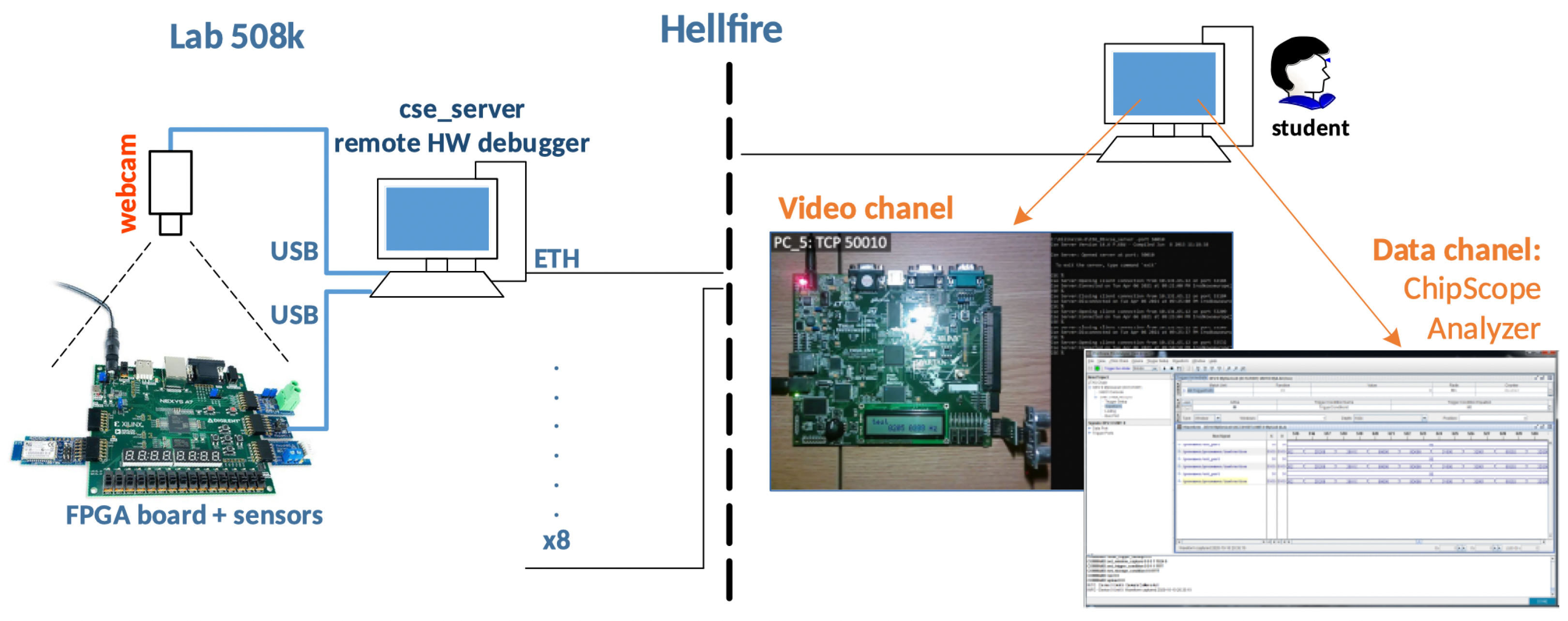
Figure 1.
System architecture for designing FPGAs operating under the IoT concept. The right side of the firewall shows the camera view that a student sees and a screen of the software used for remote programming. The left side of the firewall shows the conceptual connection between the PC and a prototype board with an FPGA chip and the connection of the webcam transmitting the image from the preview in the lab.

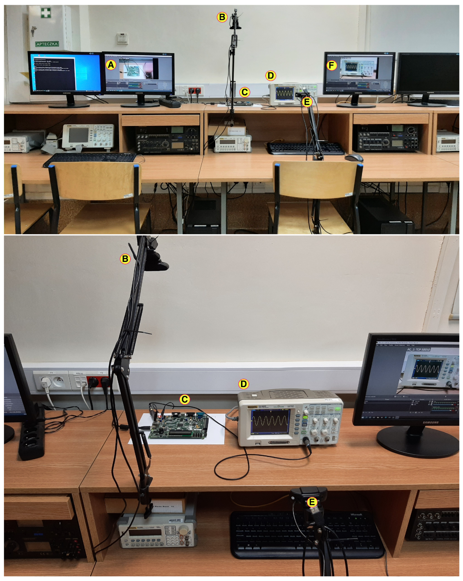
Figure 2.
One lab stand behind the firewall in Figure 1. Computer A is connected to the FPGA test board C and camera B; oscilloscope D; and camera E is connected to computer F.
Figure 2.
One lab stand behind the firewall in Figure 1. Computer A is connected to the FPGA test board C and camera B; oscilloscope D; and camera E is connected to computer F.

Figure 3.
Screen of the home page of the Fundamentals of Digital Design and Synthesis course. The interface of the ’ekursy’ platform is in the Polish language. 1—Course name, 2—announcement section, 3—help forum, 4 and 5—links to the audio and video communicators, 6—remote connection procedure instruction, 7—FPGA programming test files, 8—section with embedded twich.tv channels, 9—basic information about the course, 10—student course evaluation, 11—section related to remote access, 12—section with lectures on VHDL (VHSIC Hardware Description Language), 13—section with VHDL tasks, 14—section with lectures on programmable logic devices, 15—section with ISE tasks, 16—final project exam, 17 and 18—additional materials and tutorials, and 19—user name.

Figure 4.
The steps required for remote access (see the text below).

Figure 5.
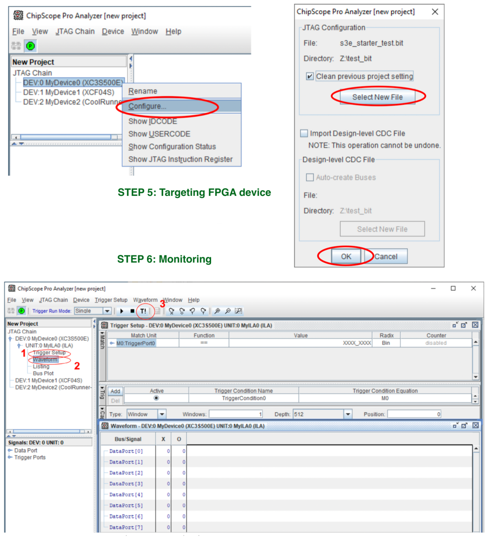
Remote programming and simulation. All steps are performed remotely from the students’ home computers. The detection of devices on the test board is confirmed by creating a tree with DEV0-DEV2 positions in the JTAG Chain section. The FPGA to be programmed is the XC3S500E. To simulate a test project, the following steps are needed: 1—open the trigger window, 2—open the time waveform window and 3—force the measurement trigger signal.
Figure 5.
Remote programming and simulation. All steps are performed remotely from the students’ home computers. The detection of devices on the test board is confirmed by creating a tree with DEV0-DEV2 positions in the JTAG Chain section. The FPGA to be programmed is the XC3S500E. To simulate a test project, the following steps are needed: 1—open the trigger window, 2—open the time waveform window and 3—force the measurement trigger signal.

Figure 6.
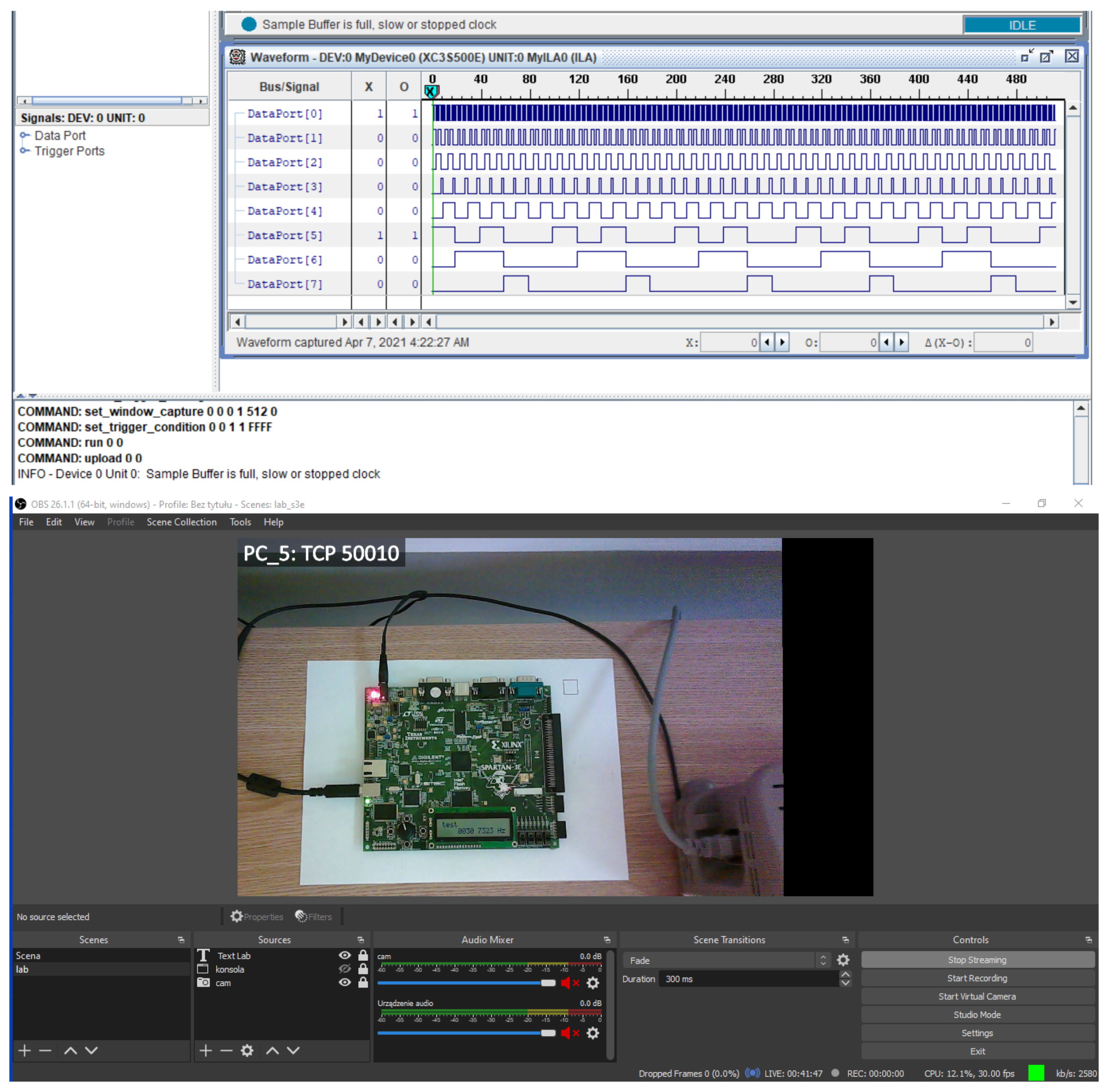
(Top) The measurement results of a counter based on a frequency divider frequency for a Spartan-3E Board. On the DataPort[0] channel, the frequency of 50 MHz is present. Subsequent channels show frequency waveforms with half the frequency of the previous channel. (Bottom) The Spartan 3e board configuration with a counter (based on a frequency divider).
Figure 6.
(Top) The measurement results of a counter based on a frequency divider frequency for a Spartan-3E Board. On the DataPort[0] channel, the frequency of 50 MHz is present. Subsequent channels show frequency waveforms with half the frequency of the previous channel. (Bottom) The Spartan 3e board configuration with a counter (based on a frequency divider).

Figure 7.
The unit designed for temperature and humidity sensing.

Figure 8.
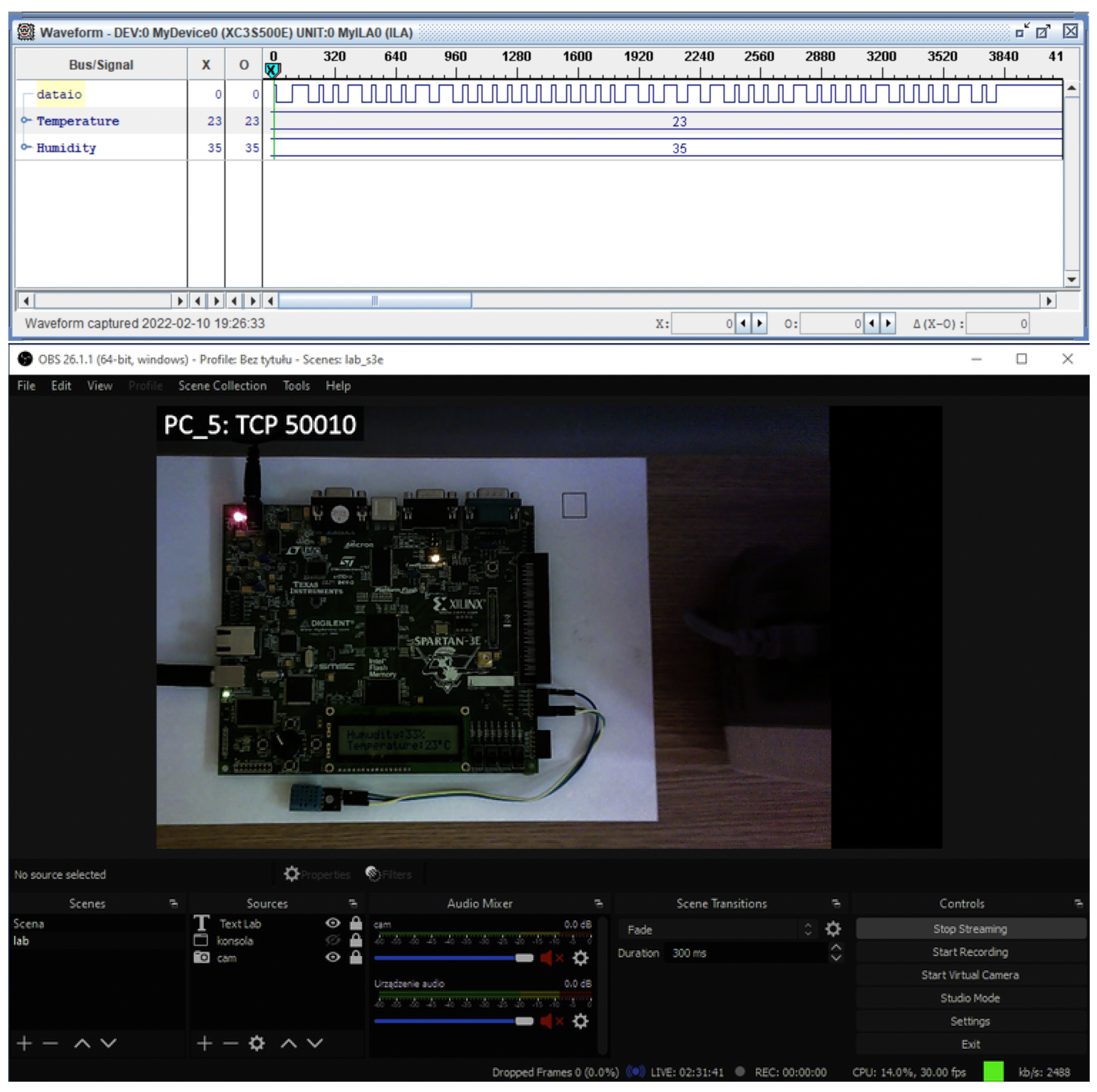
(Top) The chipscope temperature (in °C) and humidity (in %) readings. (Bottom) Monitoring the reading of the physical sensor data via the OBS environment in the lab room.
Figure 8.
(Top) The chipscope temperature (in °C) and humidity (in %) readings. (Bottom) Monitoring the reading of the physical sensor data via the OBS environment in the lab room.

Figure 9.
The DAC_TOP (designed sinusoidal waveform generator) along with its simulation results in different time intervals. The control signals are: —sends commands and data to the DAC, —resets the DAC, —SPI clock to the DAC, —selects the SPI device to communicate with in this case, it is the DAC.

Figure 10.
A preview of two channels. The design of the sine wave generator does not require the use of an LCD display. The first video channel is only for visual inspection of the oscilloscope probe connection.
Figure 10.
A preview of two channels. The design of the sine wave generator does not require the use of an LCD display. The first video channel is only for visual inspection of the oscilloscope probe connection.


Table 1.
Paper doi information: 1 (10.1109/TAEE46915.2020.9163676), 2 (10.1109/TAEE46915.2020.9163688), 3 (10.3390/educsci9030222), 4 (10.3390/electronics10182191), 5 (10.1109/TAEE46915.2020.9163773), 6 (10.3390/electronics10182229), 7 (10.1109/FIE43999.2019.9028694) and 8 (this paper).
Table 1.
Paper doi information: 1 (10.1109/TAEE46915.2020.9163676), 2 (10.1109/TAEE46915.2020.9163688), 3 (10.3390/educsci9030222), 4 (10.3390/electronics10182191), 5 (10.1109/TAEE46915.2020.9163773), 6 (10.3390/electronics10182229), 7 (10.1109/FIE43999.2019.9028694) and 8 (this paper).
| Verification through Representative Examples | Remote Viewing of Measuring Equipment Present in a Lab | System with a Dedicated Image of a Virtual Machine | System Uses Virtual Programs Imitating Physical (Real) Equipment | Integration with Internal University Teaching Network | |
|---|---|---|---|---|---|
| 1 | no | no | no | no | no |
| 2 | yes | no | no | no | no |
| 3 | yes | no | no | yes | no |
| 4 | no | no | no | yes | no |
| 5 | no | no | no | yes | no |
| 6 | yes | no | no | yes | no |
| 7 | yes | yes | no | yes | no |
| 8 | yes | yes | yes | no | yes |
Publisher’s Note: MDPI stays neutral with regard to jurisdictional claims in published maps and institutional affiliations. |
© 2022 by the authors. Licensee MDPI, Basel, Switzerland. This article is an open access article distributed under the terms and conditions of the Creative Commons Attribution (CC BY) license (https://creativecommons.org/licenses/by/4.0/).
Share and Cite
MDPI and ACS Style
Melosik, M.; Naumowicz, M.; Kropidłowski, M.; Marszalek, W. Remote Prototyping of FPGA-Based Devices in the IoT Concept during the COVID-19 Pandemic. Electronics 2022, 11, 1497. https://doi.org/10.3390/electronics11091497
AMA Style
Melosik M, Naumowicz M, Kropidłowski M, Marszalek W. Remote Prototyping of FPGA-Based Devices in the IoT Concept during the COVID-19 Pandemic. Electronics. 2022; 11(9):1497. https://doi.org/10.3390/electronics11091497
Chicago/Turabian StyleMelosik, Michał, Mariusz Naumowicz, Marek Kropidłowski, and Wieslaw Marszalek. 2022. "Remote Prototyping of FPGA-Based Devices in the IoT Concept during the COVID-19 Pandemic" Electronics 11, no. 9: 1497. https://doi.org/10.3390/electronics11091497
Note that from the first issue of 2016, this journal uses article numbers instead of page numbers. See further details here.