
The new bud light steel system and the geometric shape evolution of light steel framework for COVID-19 patients appointed hospital (Huoshenshan hospital)
Abstract
The light steel structure is always the common material of the movable plank house, and the new bud light steel system is the light steel system used for a long time after the earthquake. This paper discusses the mechanical system of the light steel structure of Huoshenshan hospital, which was built in ten days. In the process of building, the geometric form of roof stress has changed. In the actual structural design, the designer seldom takes the calculation of construction load into account, which is quite different from the actual construction process. So it is very important to simulate and monitor the whole process of structure installation. In this paper, the finite element software MIDAS / Gen is used for simulation analysis to ensure that the simulation analysis results are consistent with the construction process, the model material and the actual size are completely consistent, and the stress simulated by the software can meet the needs of the actual stress through the actual measurement.
1Introduction
Novel corona virus hospital in Wuhan is located in Caidian District, Wuhan. It is a special hospital built in Wuhan staff sanatorium based on the “Beijing Xiaotangshan Hospital” model during the fight against SARS in 2003. The hospital has a total construction area of 33900 square meters, 1000 beds, ICU, and general wards, auxiliary departments such as infection control, inspection, special diagnosis and radiation diagnosis, and no outpatient service [1, 2].
On January 23, 2020, Wuhan Urban Construction Bureau urgently convened the Third Construction Bureau and other units to hold a special meeting. On January 24, 2020, the relevant design scheme of Wuhan Huoshenshan hospital was completed; on January 29, 2020, the construction of Wuhan Huoshenshan hospital has entered the critical period of ward installation; on February 2, 2020, at noon, Wuhan Huoshenshan hospital was officially delivered. It only takes 10 days from the design to the construction, which is known as China’s speed.
Xinya light steel (construction) system (abbreviated as Xinya system) is a highly integrated construction system conceived by the team of architects of the Chinese University of Hong Kong on the basis of movable plank houses. The core problem the system tries to solve is the contradiction between “rapid construction and building quality":
1. Solve the structural and enclosure problems of light steel buildings through the integrated design of building structure and enclosure plate, especially to eliminate the cold bridge phenomenon of light steel frame;
2. Through the flexible use of the plane layout and the exterior skin of the building, a rich space form is formed to meet the adaptation of the building to different sites [3–8].
This improved light steel maintenance structure and maintenance system, on the one hand, can be factory prefabricated and installed as common steel structure. In addition, it also has a small volume of transportation, easy to build, built indoor ventilation, heat preservation, heat insulation and other aspects of the comfortable type can also meet the needs of modern life [9, 10].
After the “May 12” Wenchuan earthquake in 2008, there are billions of movable plank houses used for turnover in the transitional period, as the temporary residence and teaching place for the people in the disaster area. On this basis, if the cost of 300 yuan / m2 is calculated, the area of movable plank houses built in the disaster area may be close to 10 million m2. However, negative reports about it are not uncommon. For example, in summer, students in these temporary classrooms sometimes suffer from extreme heatstroke or even fainting. Although the service life of these temporary buildings can be calculated in years, with the completion of the resettlement houses, they are largely vacant or even abandoned by the local people in just a few months. As a result, these abandoned plank houses either become garbage or need professional strength for recycling. It is not hard to imagine that only the loss of building materials and the repeated allocation of human resources consume a lot of social resources, regardless of the recovery efficiency. This phenomenon reflects both sides of the construction system. On the one hand, it has incomparable advantages of heavy-duty system, which can be quickly assembled, low price, safe and earthquake resistant, can be disassembled and disassembled many times, and can save manpower, which fully meet the needs of structures in the emergency stage; on the other hand, its indoor thermal physical performance is intolerable, typical “hot in summer and cold in winter", and there is only difference between indoor and outdoor weather. Other defects will not be discussed in this paper, such as the symbolic blue roof and white wall appearance, which is related to the “work shed” and the lower social status. For the end user, the issue of comfort is far more important than the construction process.
Huoshenshan hospital has developed continuously in the 12 years after Wenchuan, forming a unique construction speed, and the unique light steel structure solves the problem of cold winter and hot summer. During the construction of Huoshenshan hospital, the construction process is shown below.
2Simulation analysis of the whole construction process of Huoshenshan hospital
The construction of spatial structure is a continuous process, and the stress form and deformation state of structure is also a continuous process. The deformation and internal force of the structure in the former construction process will inevitably affect the deformation and internal force in the latter construction process, so it is very necessary to monitor and analyze the structural construction process. The main content of this chapter is to use MIDAS / Gen to simulate the whole construction process of the steel structure truss of Huoshenshan hospital, providing the basis for the rational construction of the structure and the reasonable monitoring of the whole construction process.
2.1Project overview
Novel corona virus hospital in Wuhan is located in Caidian’s Caidian District, Wuhan. It is a special hospital built in Wuhan staff sanatorium based on the “Beijing Xiaotangshan Hospital” model during the fight against SARS in 2003. The hospital has a total construction area of 33900 square meters, 1000 beds, ICU, ICU and general wards, auxiliary departments such as infection control, inspection, special diagnosis and radiation diagnosis, and no outpatient service.
Huoshenshan hospital is a multi-storey building structure with four floors above the ground and one floor underground in some areas. The total height of the building is 19.6 m. The main structure of the lower part of the hospital is reinforced concrete structure, and the roof of the upper part is steel structure. Because the roof of Huoshenshan hospital is huge, and each member is determined by welding connection, and the stress is relatively complex, which adds great difficulties to the construction process. Therefore, in order to ensure the safety of the structure and the correctness and rationality of the installation scheme in the whole process of construction, it is very important to simulate the whole process of structure construction and monitor the whole process of installation construction. And it means a lot.
The steel structure roof of Wuhan Huoshenshan hospital adopts the spatial truss structure, with the plane of rectangle and the size of 79.2×58.4 m. It is composed of 12 main trusses, 10 Zhicheng trusses and 4 side trusses. The upper and lower chord supporting systems are arranged in the roof, and the raceway is welded with the truss. The upper roof is a conical roof composed of steel structure. The support of the upper steel structure system is located on the top of the lower reinforced concrete column, and the rubber pad is embedded on the top of the column, which is connected by the embedded bolt (the bolt adopts double nuts), and the load is transmitted to the column through the column top. The transmission system of Huoshenshan hospital roof is that the load is transmitted to the main truss through the secondary truss, and then the load is transmitted to the embedded screw on the top of the column through the main truss, and then the embedded screw on the top of the column is transmitted to the column to enter the foundation. The transmission of the whole structure is very clear and the stress is relatively simple.
2.2Key points and difficulties in the construction of steel structure buildings
According to the characteristics of site selection, reasonably determine the isolation and protection from the outside, health and epidemic prevention and environmental protection measures, site arrangement, internal and external traffic organization, functional division, building and facility layout, and fire rescue, etc. The formulation of this strategy is the key to determine the construction progress, which needs to be considered from macro to detail. Once there is a mistake, there is almost no room for turning back, which is likely to lead to the failure of the whole emergency project.
Huoshenshan hospital is located on the Bank of Zhiyin lake, Caidian District, Wuhan city. Its site is adjacent to the existing Wuhan staff sanatorium. The current site is a wasteland, with some ups and downs. There are a group of temporary buildings and a 3-storey small building on the ground except for weeds and trees.
The biggest advantage of the site selection is that the building complex outside the north end of the base is an unfinished project, and the East and south sides of the base are open lakes, which is very conducive to the isolation and protection of the hospital and the outside world. However, there are many problems to be solved in the site selection. Here are some key points:
(1) Zhiyin lake is an important lake system in Wuhan City, which should be protected without fail. (2) There are residential areas already occupied on the west side of the land, so the separation of physical space and psychological space should be considered. (3) There is only one urban road on the west side of the base, and transportation during construction may form a bottleneck. (4) The site is uneven, with a maximum height difference of about 10 m. the site leveling work volume is large, which will occupy a lot of construction period. Therefore, the corresponding technical scheme should be selected on the premise of the principle of the shortest construction period. (5) The vertical relationship between the site and the perennial water level and the highest water level of Zhiyin Lake shall be considered. (6) It is necessary to minimize the adverse effects of the existing staff sanatorium as the living security area of medical staff located in the downwind side of the medical isolation area.
In response to the above problems, the following strategies are adopted:
(1) It is determined that the minimum building elevation of the site is not lower than the outdoor ground of the building at the lowest place of the existing sanatorium, and the rainwater on the ground is collected and disinfected in a fast drainage mode. In order to prevent the surface water from seeping, the whole base is covered with anti-seepage membrane to ensure that “one drop of water does not enter the lake and one drop does not seep";
(2) Increase the isolation and protection distance with the adjacent urban road and the East residential area as much as possible. In fact, it is 40 m away from zhiyinhu Avenue and no less than 120 m away from the nearest residence on the west side. The medical buildings along zhiyinhu Avenue are bungalows, and the isolation barrier is set on the side along zhiyinhu Avenue;
(3) On the premise that the minimum construction site is no less than the existing sanatorium, the site is divided into two platforms on the principle that it is most conducive to speed up the construction progress, all earthwork is balanced and digested in the site, and the elevation difference treatment at each joint of the site is properly handled to ensure the vertical connection of the traffic organization is smooth;
(4) By forming a medical isolation area around the ring road of the newly-built medical room, the distance between the newly-built medical room and the nearest building of the adjacent sanatorium shall be more than 20 m, so as to meet the requirements of the current code for architectural design of infectious disease hospitals. In order to minimize the adverse impact of the medical isolation area located on the windward side, an open space of no less than 130 m shall be reserved between the 2 inpatient building and the sanatorium to facilitate the diffusion of air flow through the medical area;
(5) The building layout adopts the fish bone intensive layout mode, which maximizes the number of beds by building more wards. Meanwhile, it tries to avoid the passage of medical staff in the outdoor space of the isolation area and the crossing of the outdoor path with the patient;
(6) Limited to the condition that there is only one urban road outside, only an entrance for transferring patients is opened at the intersection of the north boundary of the base and zhiyinhu Avenue. Medical staff and cleaning logistics make full use of the existing gate of the sanatorium, thus forming a one-way streamline from south to north, from cleaning to pollution. The ring road around the medical room is also the fire lane. The patients in the isolation area are connected by ferry car from the reception office to each ward building through the ring road, which is simple and efficient, and avoids the complex indoor traffic organization. More importantly, it reduces the housing work volume and maximizes the short work period;
(7) The setting of all supporting facilities shall be based on the principle of reliability, practicality, easy maintenance and minimum work quantity. In addition to the facilities that must be set in the isolation area such as waste disposal and negative pressure suction station, the rest of the power supply and distribution, oxygen station, rainwater collection and disinfection storage tank, sewage treatment and dosing station are set outside the isolation area, and the equipment that can be operated in the open sky shall be used as far as possible. There is also an ambulance decontamination station at the entrance and exit of the patient transfer. After the ambulance completes the transport task, it must be decontaminated before leaving.
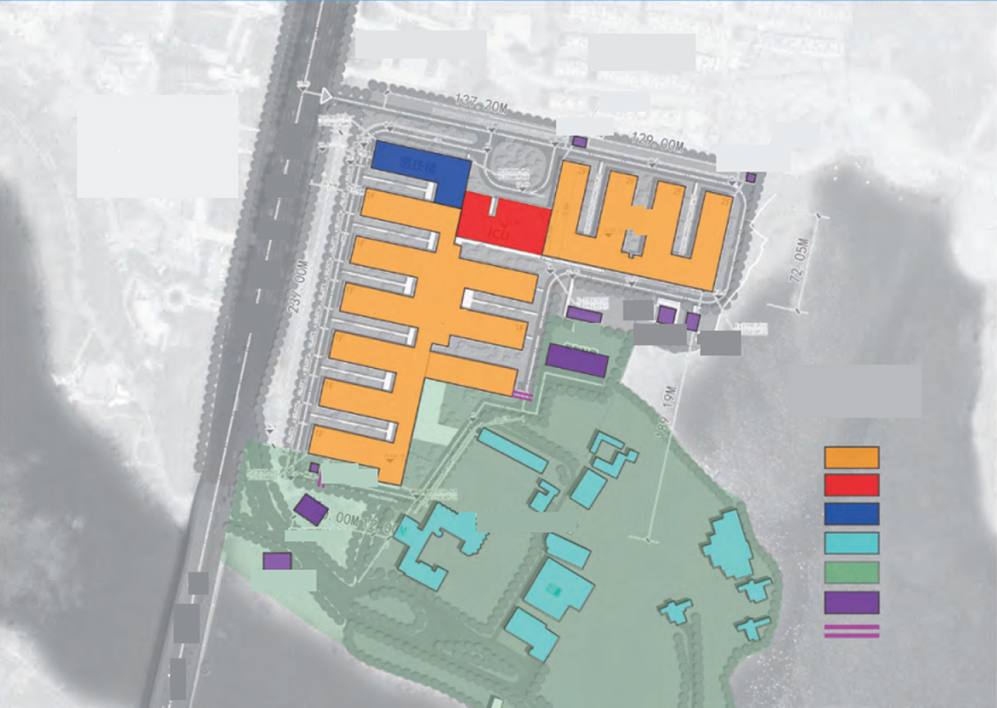
The final design drawing is shown in Fig. 1.
Fig. 1
Functional division of Huoshenshan hospital.
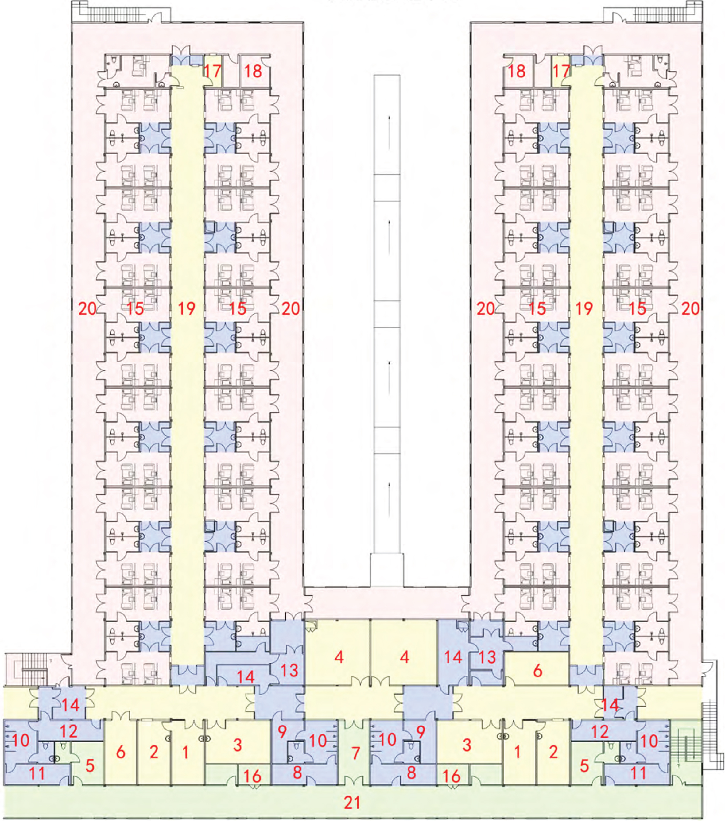
Take unit 2 of Huoshenshan ward building as an example. The structure of the building is shown in Fig. 2. Among them, the interval of related functional areas is divided into columns of light steel structure, and the change of its geometry uses various structures to achieve the related functions.
Fig. 2
Standard unit of ward building 2 of Huoshenshan hospital (1 Nurse station; 2 Dispensing room; 3 Health care office; 4 Supplies storeroom; 5 Health care lounge; 6 Medicine library; 7 Passing room; 8 First changing room (male); 9 Second changing room (male); 10 Shower room; 11 First changing room (female); 12 Second changing room (female); 13 Take off isolation gown; 14 Take off protective suit; 15 Wards; 16 Electrical room; 17 Nurses’ office; 18 Boiling water; 19 Semi-contaminated passage; 20 Contaminated passage; 21 Clean passage).
3Establishment of finite element model
Due to the huge span and area of the project, light steel structure is adopted, but the self weight is also huge, so the comprehensive installation method of integral hoisting and high-altitude bulk method is finally determined. For each main truss, it is directly assembled on the ground of the construction site and then hoisted to the design position with lifting equipment. For other secondary trusses and connecting members, it is directly welded at high altitude. Because this can reduce the use of many temporary supports, reduce the amount of work at height, shorten the construction period, ensure the quality of construction, reduce the level of lifting equipment, and reduce the cost. The installation sequence of the main truss is gradually lifting from the outside to the inside. After lifting, the secondary truss members between the two main trusses will be welded and connected. As the main truss is gradually installed and constructed from the inside, the secondary truss members will be welded and connected gradually. Finally, the main truss and the secondary truss connecting members will be welded and the raceway will be installed.
The unloading plan of the temporary support of the project is based on the distribution of the actual members after hoisting and the stress and deformation characteristics of the structure from the outside to the inside.
The main loads considered in this paper are the self weight of the structure and the construction load. Because the construction load is far less than the self weight of the structure, the self weight load of the structure plays a decisive role in the construction. The roof structure layout of the project is from left to right in the order of axis 1-12, that is, the main truss is from left to right in the order of the first truss to the twelfth truss, and the spacing of each main truss is 7.2 m except that the spacing between spans 1-2 and 11-12 is 7.1 m. Considering the actual installation construction scheme of the project, according to the simulation analysis of the whole structure under its own weight, this paper selects the sixth main truss for the construction process analysis, and then converts the mass of the connecting members of the fifth main truss, the seventh main truss and the sixth main truss into the self weight load to the sixth through the following formula. Due to the continuous construction, the load on the structure will gradually change. The change of internal force and deformation of the sixth truss member is obtained through the gradual change of load. Whether the changes of internal force and stress-strain meet the requirements of code for design of steel structures is analyzed. The steel pipe of the project is hot-rolled seamless steel pipe or straight seam welded steel pipe.
According to the design requirements, the dead load value of the roof of the project is 1 kn / m2, the horse road load and hanging load value of the lower chord is 0.5 kn/m2, the live load of the roof is 0.7 kn/m2, the live load of the lower chord of the roof truss is 1 kn / m2, and the basic snow pressure is 0.6 kn/m2.
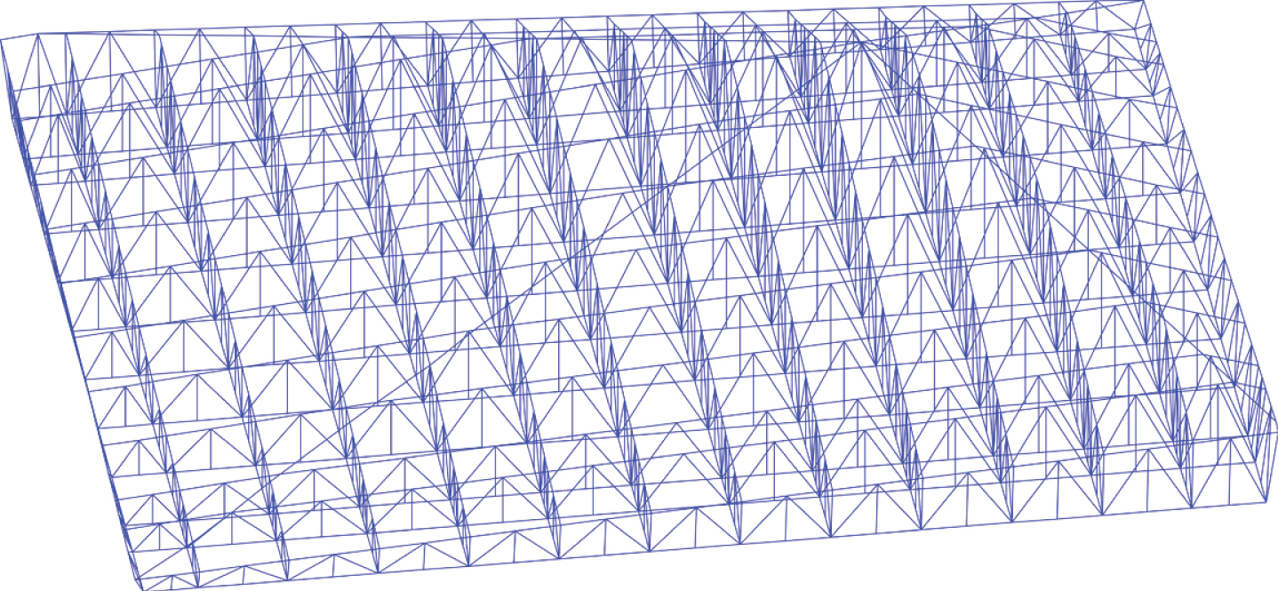
Midas / Gen, a finite element software, is used for the simulation analysis of the project. In order to ensure that the simulation analysis results are accurate and consistent with the actual construction process, the material properties and size in the model are the same as the actual structure, and the overall model of the structure is as follows:
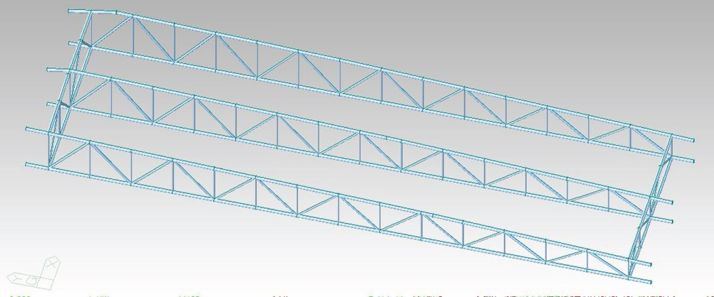
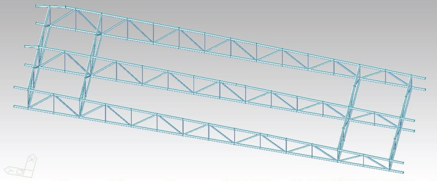
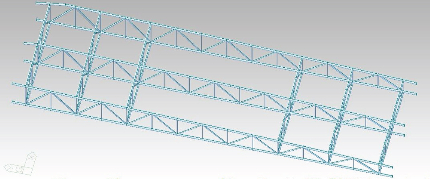
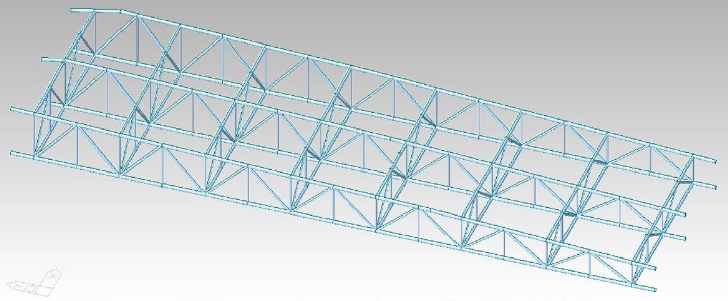
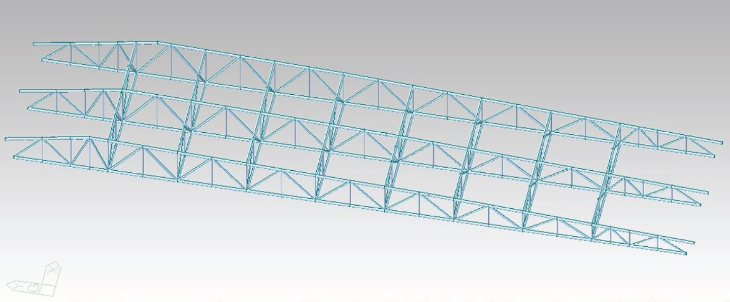
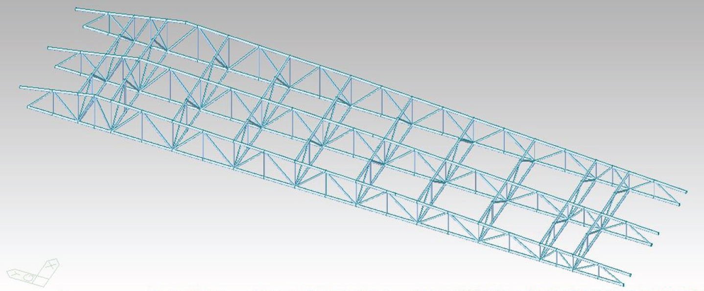
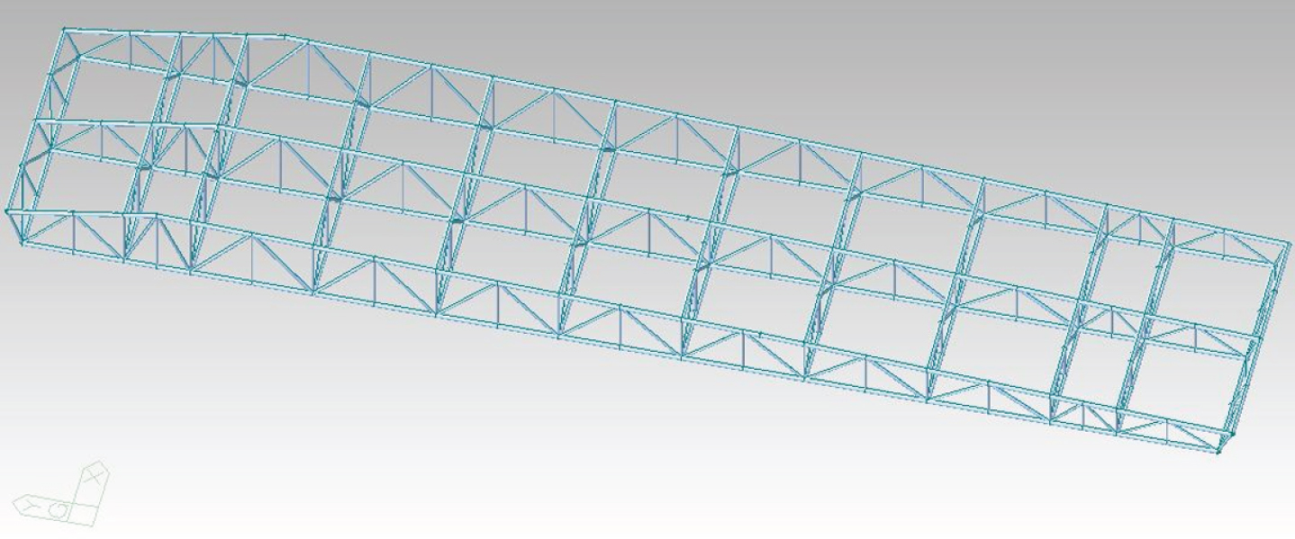
The finite element analysis of light steel is shown in Fig. 3.
Fig. 3
Axonometric map of Huoshen Mountain House.
The internal force and deformation of Huoshenshan hospital model under the action of self weight are shown in the following figure. According to the comparison of internal force and deformation of each main truss, the change rule of the sixth main truss is representative, and the maximum and minimum values of internal force and deformation are reflected in this truss. For the convenience of research and the reason of this paper, the fifth, sixth and seventh main trusses are selected in this paper The construction process is simulated and analyzed by the composed unit.
The displacement contour and deformation diagram of the coordinate Z direction under the self weight of the hospital are shown in Fig. 4.
Fig. 4
Displacement isoline and deformation diagram of Z-direction coordinate under self weight of hospital.
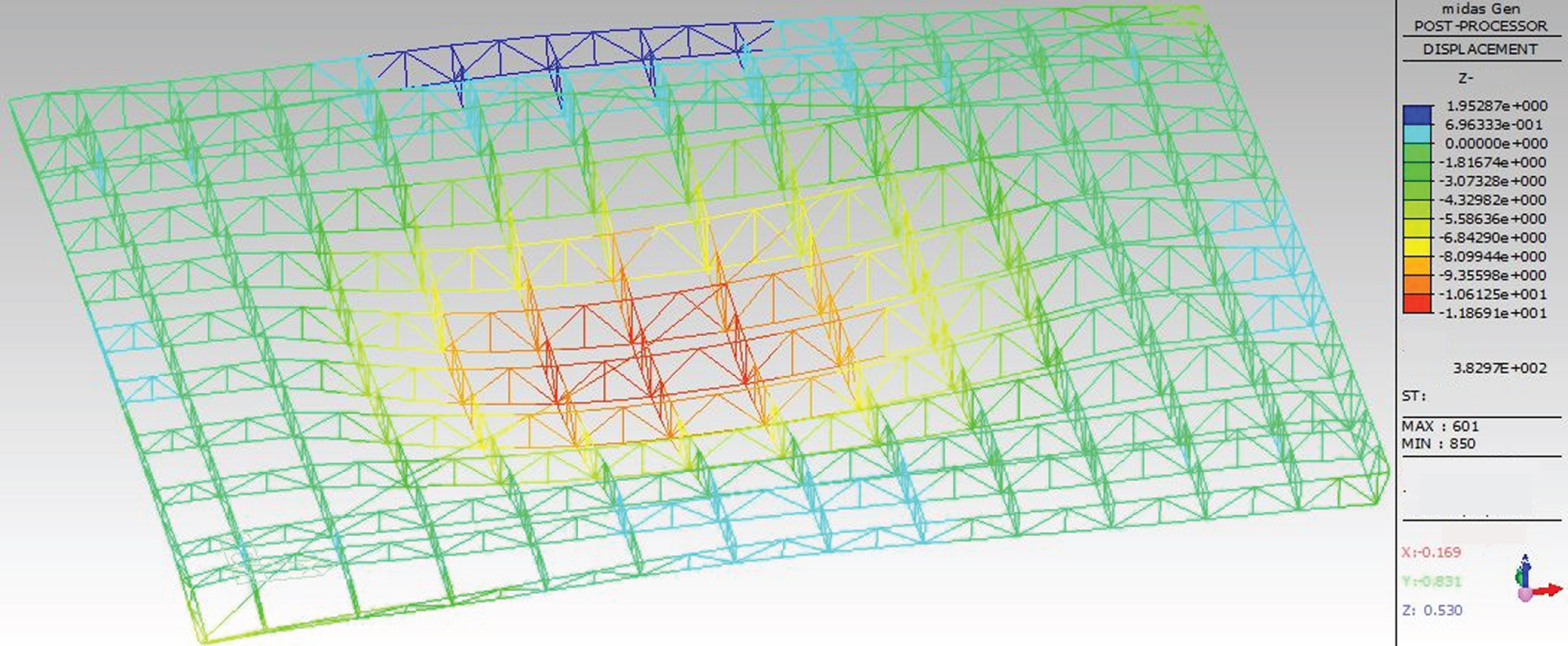
Because the actual deformation of structural members is very small, in order to facilitate the study and inspection, the graphic magnification is used to display. The magnification factor in the right side of the figure above is the magnification of the actual deformation of the structural member. Under the action of self weight, the maximum downward displacement of the whole structure on coordinate Z is 11.87 mm, and the maximum upward displacement is 1.95 mm, which is smaller than the maximum L/400. 117 mm, in the code for design of steel structures.
Because the actual deformation of structural members is very small, in order to facilitate the study and inspection, the graphic magnification is used to display. The magnification factor in the right side of the figure above is the magnification of the actual deformation of the structural member. Under the action of self weight, the maximum downward displacement of the whole structure on coordinate Z is 11.87 mm, and the maximum upward displacement is 1.95 mm, which is smaller than the maximum L / 400, i.e. 117 mm, in the code for design of steel structures.
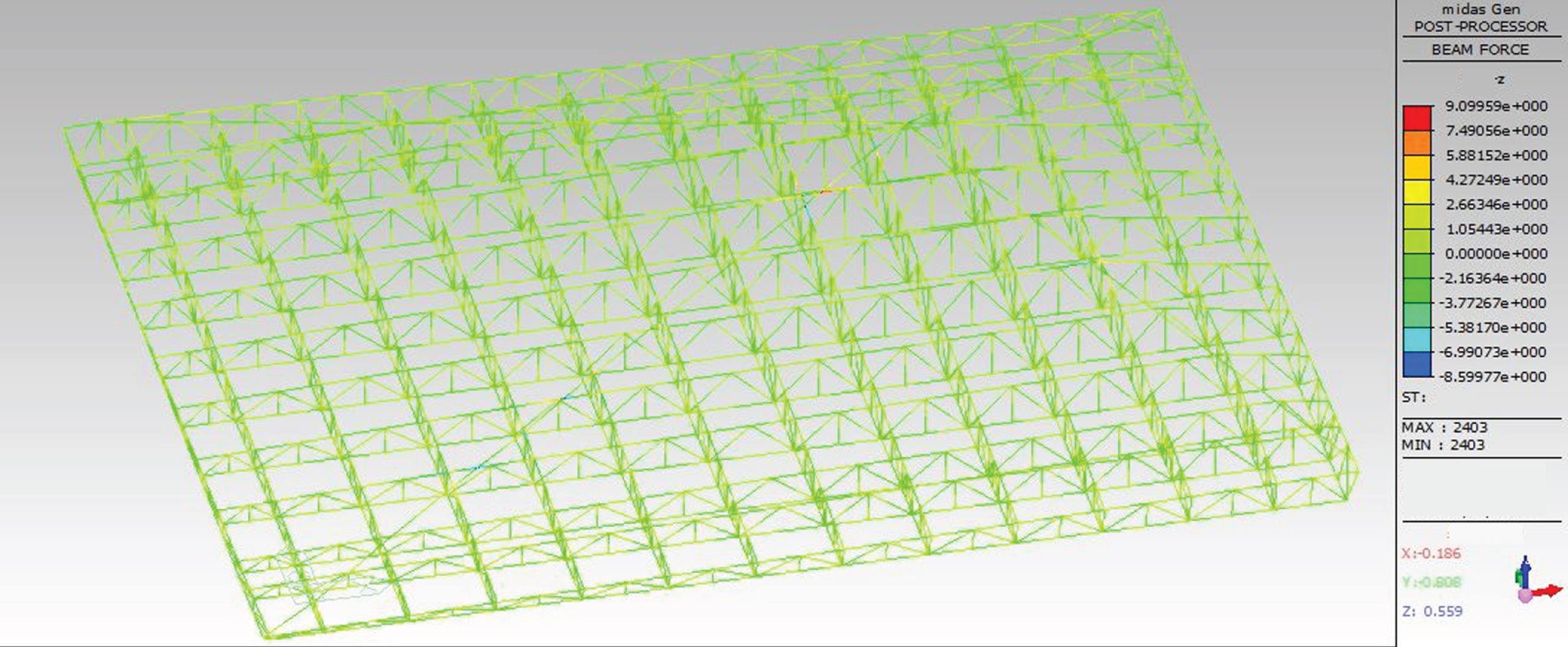
As shown in Fig. 5, the negative sign in the figure on the right indicates the tension at the lower part of the member, otherwise, it indicates the tension at the upper part of the member. The maximum positive bending moment and negative bending moment of members in coordinate Z direction are 9.10 kn * m and 8.60 kn * m respectively, but the bending moment of most members is about 2 Kn * m.
Fig. 5
Bending moment diagram of hospital roof in coordinate Z direction under self weight.
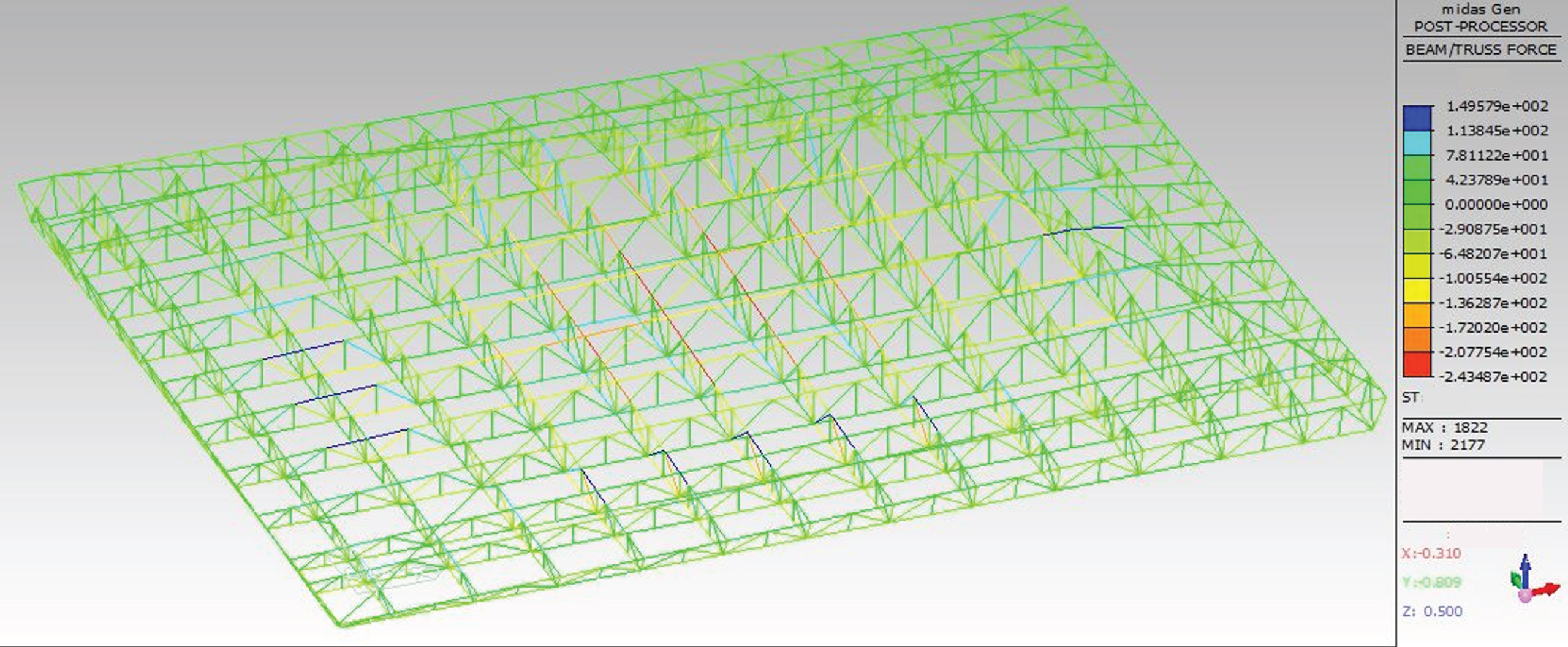
The minus sign in front of the value on the right side of Fig. 6 indicates that the bearing force of the structural member is pressure, otherwise, no minus sign indicates that the bearing force of the structural member is tension. The figure above shows that the maximum pressure of the whole structure under the self weight is 243.49 kN and the maximum tension is 149.58 kN.
Fig. 6
Axial diagram of each member of hospital roof under self weight.
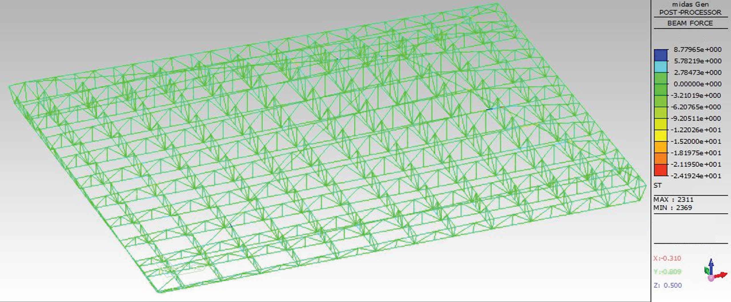
The minus sign in front of the value on the right side of Fig. 7 indicates that the direction of the shear force turns counterclockwise with respect to the member, otherwise, no minus sign indicates that the direction of the shear force turns clockwise with respect to the member. The figure above shows that the maximum shear force of the whole structure under self weight is 24.19 kN.
Fig. 7
Shear diagram of each member in coordinate Z direction under self weight of hospital roof.
4Simulation analysis of construction process
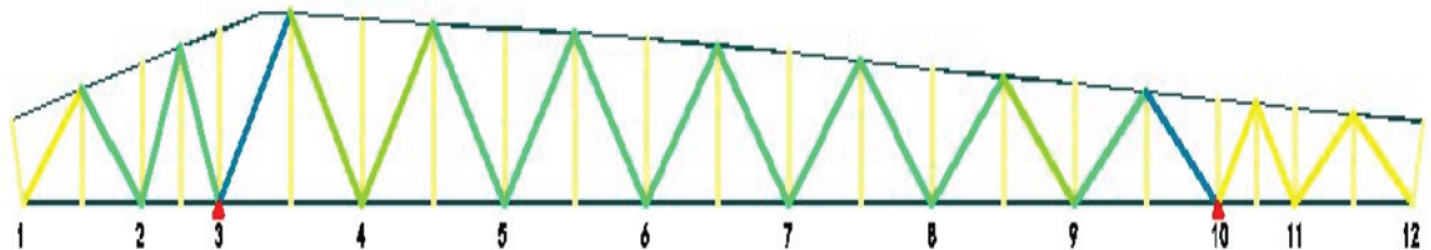
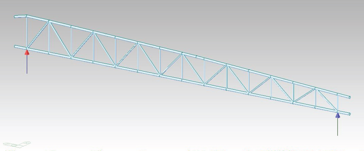
The analysis model is built to make it coincide with the actual construction process as much as possible to ensure the practicability and feasibility of simulation. According to the installation scheme introduced above, on the basis of the overall finite element model, the sixth main truss is selected for simulation. Firstly, all members except this truss are passivated, and then the corresponding components, boundaries and loads are activated respectively to simulate the whole construction process of the structure. This can not only meet the continuity of the construction process, but also ensure that the deformation and internal force generated in the previous working condition can be included in the next working condition, and more reflect the whole process of the actual construction. In order to facilitate the research and explanation, the connection points of the secondary trusses of the five, six and seven main trusses are numbered as shown in the figure below.
Where Δ in Fig. 8 is the location of the support, and the supports of subsequent numerical models are the connection of this location.
Fig. 8
Connection point number diagram.
Condition 1: the sixth truss is lifted and fixed separately after splicing on the ground, and then simulated and analyzed under its own weight, which is shown in Fig. 9.
Fig. 9
Working condition the first mock exam.
Condition 2: after the fifth truss and the seventh truss are hoisted up, the installation of connection point 3 and connection point 10 is carried out, and then the simulation calculation of the installed components under the self weight is carried out, which is shown in Fig. 10.
Fig. 10
Working condition 2 model diagram.
Condition 3: the installation of connection point 4 and 9, and then the simulation calculation of the installed components under the self weight, which is shown in Fig. 11.
Fig. 11
Working condition 3 model diagram.
Condition 4: the installation of connection point 5 and 8, and then the simulation calculation of the installed components under the self weight, which is shown in Fig. 12.
Fig. 12
Working condition 4 model diagram.
Condition 5: the installation and construction of connection point 6 and 7 are carried out, and then the simulation calculation of the installed components under the self weight is carried out, as shown in Fig. 13.
Fig. 13
Working condition 5 model diagram.
Condition 6: the installation and construction of the cantilever members on both sides of the fifth, sixth and seventh trusses, and then the simulation calculation of the installed members under the self weight. As shown in Fig. 14.
Fig. 14
Working condition 6 model diagram.
Condition 7: the installation and construction of connection point 2 and connection point 11 are carried out, and then the simulation calculation of the installed components under the self weight is carried out, as shown in Fig. 15.
Fig. 15
Working condition 7 model diagram.
Condition 8: the installation and construction of connection point 1 and 12 are carried out, and then the simulation calculation of the installed components under the self weight is carried out, as shown in Fig. 16.
Fig. 16
Working condition 8 model diagram.
Condition 9: the installation and construction of the upper connecting rod of the truss at the lower part of the upper chord support, and then the simulation calculation of the installed components under the self weight.
Condition 10: the installation and construction of the upper connecting rod of the high truss supported by the top chord, and then the simulation calculation of the installed components under the self weight.
Condition 11: for the installation and construction of the overall raceway, since this paper only studies the simulation calculation of three trusses, after the installation and construction of the raceway, load the raceway load and the hanging load of the lower chord onto the truss node, and then carry out the simulation calculation of the installed components in this case.
Condition 12: after the installation of roof panel, the combination of self weight of roof panel and snow load is converted into concentrated load to load on the truss node, and then the simulation calculation of installed components is carried out in this case.
For the convenience of research and explanation, and due to space limitation, this paper takes several representative member elements in the process of force change for research. The selected member unit is shown in Fig. 17.
Fig. 17
Node No. and measuring point no. of the sixth truss.
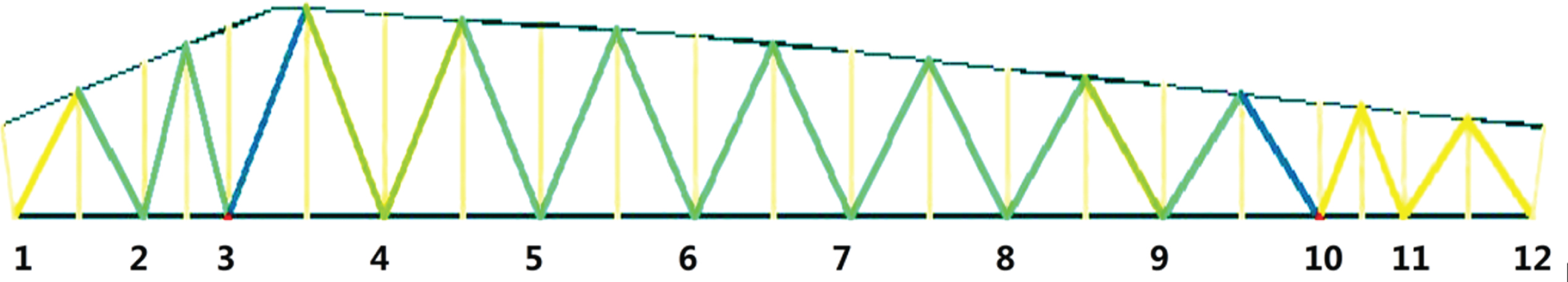
The position shown in figure 0 is the member studied in this paper, and Δ is the support position.
The internal force and deformation value of the member element in each working condition simulation study are shown in the following list.
It can be seen from the above table that the stress of each member increases slowly with the continuous construction, but the change is very gentle. This shows that the stress of the member increases gradually in the construction process, and gradually enters the design state from the construction state. There is no stress mutation in the whole process, indicating that the construction scheme is appropriate. At the same time, the absolute value of the maximum stress of the member is 69.3 n/mm2, far less than the allowable stress value of 310 n / mm2, and the maximum displacement of the truss is 38.05 mm, far less than the code limit. Measuring point axial force is shown in Table 1. The whole structure is in the elastic stage, and the structural safety factor is very high, which meets the design requirements.
5Stress monitoring of steel truss in Lujiang Gymnasium
Principle of stress calculation: the principle of calculation in this paper is to use the relationship between stress and strain for conversion calculation.
Among:
σ: Stress at measuring point, in N / mm2;
E: The elastic modulus of the member is set as 2.06×10⁵ N/mm2;
ɛ: Micro strain measured on site.
Stress simulation results of measuring points is shown in Table 2. After the actual measurement of the structural force of Huoshenshan hospital, the measured results of the stress at the measuring points are shown in Table 3.
Table 1
Measuring point axial force table
| Axial force of measuring point(kN) | ||||||
| Working procedure | Measuring point No 1 | Measuring point No 2 | Measuring point No 3 | Measuring point No 4 | Measuring point No 5 | Measuring point No 6 |
| 1 | –0.2 | 64.2 | –209.4 | 60.0 | –88.6 | –97.7 |
| 2 | –0.6 | 34.2 | –209.4 | 60.0 | –89.6 | –97.7 |
| 3 | –0.6 | 80.6 | –230.5 | 65.0 | –109.2 | –109.8 |
| 4 | –0.5 | 95.6 | –274.8 | 73.0 | –124.9 | –134.5 |
| 5 | 43.9 | 110.0 | –342.0 | 100.0 | –134.4 | –160.9 |
| 6 | 65.7 | 114.1 | –319.8 | 106.3 | –115.0 | –158.8 |
| 7 | 116.0 | 117.6 | –298.6 | 105.8 | –104.1 | –156.6 |
| 8 | 116.0 | 121.5 | –283.1 | 109.1 | –77.7 | –144.6 |
| 9 | 127.2 | 125.6 | –267.1 | 115.2 | –81.3 | –156.5 |
| 10 | 106.6 | 125.1 | –258.7 | 115.2 | –81.3 | –156.4 |
| 11 | 129.2 | 168.3 | –383.5 | 119.4 | –117.4 | –209.6 |
| 12 | 299.8 | 325.3 | –494.2 | 289.4 | –198.8 | –305.9 |
Table 2
Stress simulation results of measuring points
| Axial force of measuring point(kN) | ||||||
| Working procedure | Measuring point No 1 | Measuring point No 2 | Measuring point No 3 | Measuring point No 4 | Measuring point No 5 | Measuring point No 6 |
| 1 | –2.6 | 19.5 | –20.7 | 6.8 | –10.7 | –10.1 |
| 2 | –2.7 | 19.8 | –20.7 | 6.8 | –10.7 | –10.1 |
| 3 | –3.2 | 23.8 | –22.9 | 7.2 | –12.8 | –11.3 |
| 4 | –3.7 | 27.8 | –27.9 | 8.4 | –14.8 | –13.6 |
| 5 | –4.3 | 31.9 | –35.9 | 11.6 | –16.9 | –16.5 |
| 6 | 8.5 | 32.6 | –31.5 | 11.5 | –13.3 | –15.4 |
| 7 | 11.7 | 33.8 | –30.7 | 11.5 | –11.0 | –15.1 |
| 8 | 15.8 | 34.5 | –29.6 | 11.5 | –11.2 | –14.6 |
| 9 | 16.2 | 35.6 | –27.6 | 12.3 | –11.6 | –15.3 |
| 10 | 16.2 | 35.1 | –29.5 | 12.3 | –15.6 | –11.6 |
| 11 | 19.4 | 52.6 | –37.8 | 16.2 | –15.6 | –20.3 |
| 12 | 41.6 | 47.3 | –69.9 | 27.5 | –26.7 | –35.5 |
Table 3
Table of measured results of stress at measuring points
| Axial force of measuring point(kN) | ||||||
| Working procedure | Measuring point No 1 | Measuring point No 2 | Measuring point No 3 | Measuring point No 4 | Measuring point No 5 | Measuring point No 6 |
| 1 | 5.5 | 26.6 | –10.8 | 3.1 | –8.5 | –8.8 |
| 2 | 7.8 | 28.6 | –15.6 | 7.3 | –11.4 | –11.4 |
| 3 | 23.9 | 35.6 | –19.3 | 12.5 | –16.3 | –16.2 |
| 4 | 17.6 | 29.7 | –23.3 | 13.7 | –20.4 | –20.7 |
| 5 | 29.8 | 37.6 | –38.9 | 18.2 | –15.5 | –14.9 |
| 6 | 33.6 | 45.3 | –25.9 | 19.1 | –14.6 | –14.2 |
| 7 | 35.9 | 49.6 | –28.7 | 19.8 | –16.7 | –15.8 |
| 8 | 40.9 | 52.6 | –39.6 | 20.9 | –19.8 | –19.3 |
| 9 | 43.2 | 54.8 | –46.5 | 25.6 | –19.2 | –19.5 |
| 10 | 45.6 | 56.5 | –53.7 | 29.7 | –26.3 | –18.3 |
| 11 | 47.8 | 62.9 | –62.8 | 33.8 | –36.6 | –28.8 |
| 12 | 63.6 | 62.7 | –79.6 | 39.1 | –36.5 | –39.8 |
The data in Table 3 is the stress value of the rod measured on the sixth truss under the combined action of self-weight and external load during the whole construction process of the steel truss roof of Huoshenshan hospital. The Huoshenshan steel truss is made of Q345B steel. The wall thickness of the steel pipe truss is ≤16 mm. According to the code for design of steel structures, when t≤16 mm, f = 310 n / mm2. From Table 3, it can be observed that the absolute value of stress at all measuring points is far less than the allowable value of stress, which conforms to the specification. At the same time, through calculation, it can be concluded that the stress ratio of all the above measured members is less than 25.6%, and the structure has a large bearing margin, which shows that the safety of Huoshenshan steel truss roof is very large, and the structure design is very conservative.
6Conclusions
Novel coronavirus pneumonia is a temporary hospital in Wuhan. According to the requirements of epidemic prevention and control, the construction period must be shortened on the premise of ensuring the quality and medical conditions. This puts forward high requirements for the building itself. In this paper, the mechanical system of light steel structure in huoshenshan hospital is discussed, and the whole process of structure installation is simulated and monitored. In this paper, the finite element software MIDAS / Gen is used for simulation analysis to ensure that the simulation analysis results are consistent with the construction process. The transmission system of the main building of the hospital transfers the load to the main truss through the secondary truss, and then transfers the load to the embedded screws on the top of the column through the main truss. The embedded screws on the top of the column are transferred to the column to enter into the foundation. The transmission of the whole structure is very clear and the force is relatively simple. The simulation results show that the absolute stress value of each measuring point is far less than the allowable stress value, which meets the requirements of the specification. At the same time, the simulation results show that the stress ratio of the measured members is less than 25.6%, and the structure has a large bearing margin. The novel coronavirus pneumonia patients’ temporary hospital has certain reference value.
References
[1] | Boudreault F.A. , Blais C. and Rogers C.A. , Seismic force modification factors for light-gauge steel-frame - Wood structural panel shear walls, Canadian Journal of Civil Engineering 34: (1) ((2007) ), 56–65. |
[2] | Boudreault F.A. , Blais C. and Rogers C.A. , Seismic force modification factors for light-gauge steel-frame - wood structural panel shear walls, Canadian Journal of Civil Engineering 34: (1) ((2007) ), 56–65. |
[3] | Dao T.N. and Lindt J.W.V.D. , Seismic Performance of an Innovative Light-Frame Cold-Formed Steel Frame for Midrise Construction, Journal of Structural Engineering 139: (5) ((2013) ), 837–848. |
[4] | Keerthan P. and Mahendran M. , Numerical modelling of non-load-bearing light gauge cold-formed steel frame walls under fire conditions, Journal of Fireences 30: (5) ((2012) ), 375–403. |
[5] | Osipovich A.A. , Light steel tower line designs, Electrical Engineering 70: (1) ((1951) ), 055–055. |
[6] | Osipovich A.A. , Light steel tower line designs, Electrical Engineering 70: (1) ((1951) ), 055–055. |
[7] | LaBoube R.A. , Closure of “Estimating Uplift Capacity of Light Steel Roof System", Journal of Structural Engineering 118: (3) ((1993) ), 848–852. |
[8] | Dannemann R.W. , Discussion of “Estimating Uplift Capacity of Light Steel Roof System” By Roger A. La Boube (March, Vol. 188, No. 3), Journal of Structural Engineering 119: (9) ((1993) ), 2794–2794. |
[9] | Kurata M. , Sato M. , Zhang L. , et al., Minimal-disturbance seismic rehabilitation of steel moment-resisting frames using light-weight steel elements, Earthquake Engineering & Structural Dynamics 45: (3) ((2016) ), 383–400. |
[10] | Sakumoto Y. , Hirakawa T. , Masuda H. , et al., Fire Resistance of Walls and Floors Using Light-Gauge Steel Shapes, Journal of Structural Engineering 129: (11) ((2003) ), 1522–1530. |

